


General Information12
Accessories
10833A GP-IB cable, 1 m (3.3 ft)
10833B GP-IB cable, 2 m (6.6 ft)
10833C GP-IB cable, 4 m (13.2 ft)
10833D GP-IB cable, 0.5 m (1.6 ft)
10834A GP-IB connector extender
Slide mount kit (1494-0059)
Description
The Agilent 6621A-6624A, and 6627A Multiple Output Linear Power Supplies feature a combination of programming
capabilities and linear power supply performance that make systems applications. The five models in this family offer a
total of up to 200 watts of output power, with voltages up to 50 volts and currents up to 10 amps. The output combinations
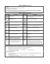
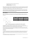
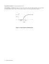
that correspond to each model are shown in Table 1-1. Each isolated output can supply power in two ranges as shown in
Figure 1-1. This flexibility allows you to use the same output to power loads with different voltage and current
requirements. No separate command is required to program ranges; the power supply automatically selects one of the
operating ranges based on the last parameter (voltage or current) that is set. Additionally, each output contains an active
downprogrammer, which means that voltage downprogramming can be accomplished as quickly as upprogramming, even
without a load.
Table 1-1. Output Combinations Available
Model Output 1 Output 2 Output 3 Output 4
Agilent 6621A 80 W Low Voltage 80 W Low Voltage - -
Agilent 6622A 80 W High Voltage 80 W High Voltage - -
Agilent 6623A 40 W Low Voltage 80 W Low Voltage 40 W High Voltage -
Agilent 6624A 40 W Low Voltage 40 W Low Voltage 40 W High Voltage 40 W High Voltage
Agilent 6627A 40 W High Voltage 40 W High Voltage 40 W High Voltage 40 W High Voltage
The output voltage and current for any output can be monitored with the front panel display. Output specific error messages
are also displayed. Front panel annunciators show the operating status of the instrument. The front panel keypad lets you set
and readback the voltage limit, current limit, and overvoltage trip level of any output. With the keypad, you can also enable
or disable outputs, mask and delay bits in the fault register, enable overcurrent protection, reset overvoltage and overcurrent
protection, and return to local operating mode.
Your multiple output power supply can be both a listener and a talker on the GP-IB. (GP-IB is Agilent Technologies’s
implementation of IEEE-488). The built-in interface is tailored to the supply, resulting in simpler programming. Voltage
and current settings can be sent directly to the specified dual range output in volts and amps.
Service can be requested from your power supply for up to ten reasons. The supply responds to a serial poll by identifying
the output on which the fault occurred. Self-contained measurement and readback capability eliminate the need for
externally scanning the outputs using a separate DVM. Upon command the supply will measure its output voltage or
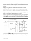
current and return the value on the GP-IB. The following functions are implemented via the GP-IB:
Voltage and current programming.
Voltage and current measurement and readback.
Present and accumulated status readback.
Programmable service request mask.
Programmable overvoltage and overcurrent protection.
Storage and recall of programmed voltage and current values for all outputs.
Queries of programmed functions or settings.
Output enable or disable.
Programming syntax error detection.