


General Information 13
Programmable delay time for service request and OCP mask.
Voltage, current, and overvoltage calibration.
GP-IB interface selftest.
Message display capability on the front panel.
Output connections are made to rear panel screw terminals. Either the positive or negative output terminal can be grounded,
or the output can be floated up to
±
240 Vdc (including output voltage) from chassis ground. Output voltage can be locally
or remotely sensed, and identical outputs can be operated in series or parallel combinations for increased output voltage or
current capability. As shipped from the factory, the power supply is jumpered for local sensing.
Your power supply can be calibrated without having to remove the cover or even having to remove it from your system
cabinet. This feature allows you to calibrate the supply at its normal operating temperature. The recommended calibration
interval is one year. Refer to Appendix A of this manual for complete calibration details. A calibration security jumper is
available inside the unit. Access is described in the service manual.
Basic Operation
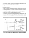
Figure 1-2 is a block diagram that illustrates the major assemblies contained within the power supply. As shown in the
figure, each supply includes a power transformer, two or more output boards, a GP-IB board, and front panel (display and
control keys).
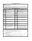
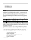
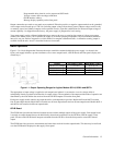
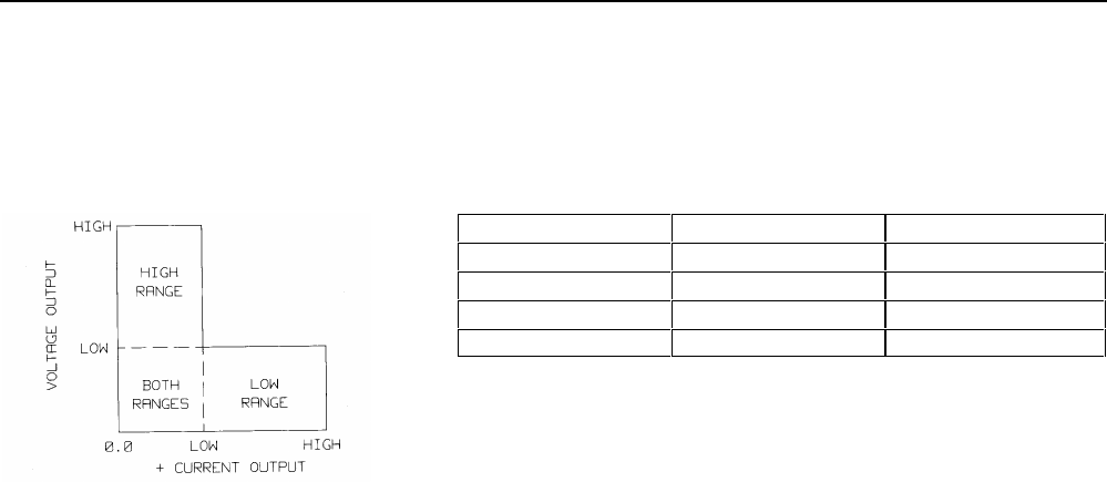
Output Low Range Values High Range Values
80 W Low, Voltage 7 V @ 10 A 20 V @ 4 A
80 W High Voltage 20 V @ 4 A 50 V @ 2 A
40 W Low Voltage 7 V @ 5 A 20 V @ 2 A
40 W High Voltage 20 V @ 2 A 50 V @ 0.8 A
Figure 1-1. Output Operating Ranges for Agilent Models 6621A, 6624A and 6627A.
The appropriate ac input voltage is applied to each output board where it is converted to a raw dc voltage which is
subsequently linearly regulated to become the dc output voltage. The magnitude of the output and the mode of operation are
determined by the load and the data received from the GP-IB computer or from the front panel.
Each power supply model contains one output board for each output that it provides. Models 6624A and 6627A contain
four 40 watt output boards; Model 6623A contains two 40 watt output boards and one 80 watt output board; Models 6621A
and 6622A each contain two 80 watt output boards.
GP-IB Board
The GP-IB board provides the interface between the user and the multiple outputs of the power supply. Each output board
is actually an output channel that can be individually selected and controlled over the GP-IB or from the supply’s front
panel. Circuits on the GP-IB board interpret commands from the GP-IB or from the front panel to control the selected
output.
The GP-IB board also processes measurement and status data received from the output boards. This data may be read back
over the GP-IB and/or displayed on the supply’s front panel.