


Remote Operation 72
Multiple Output Storage & Recall
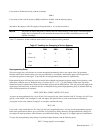
The power supply has 10 internal registers each of which can store the voltage and current settings of all the outputs. By
storing voltage and current settings for all outputs and recalling them later, you can have significant savings in
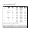
programming time. (See Supplemental Characteristics in Table 1-1).
At power-on, each of the registers contain 0 volts and the minimum current limit. To store voltage and current settings, you
must specify the register (1 to 10). For example to store the present settings of current and voltage of all your supply’s
outputs in register 2, send the following command:
STO 2
This command will take the programmed voltage and current settings of all output channels and store them in register 2.
You can set the power supply outputs to these stored voltage and current settings by sending the recall command.
RCL 2
When a register is recalled, the outputs will be set sequentially (output 1, output 2, etc.). If you attempt to recall registers
which were not previously stored, then the supply will return the power-on values for that register (0 volts and minimum
current limit). If you recalled registers outside the 1 to 10 range, you will get a number range error.
The Clear Command
This command will return the power supply to its power-on state and all parameters are returned to their initial power-on
values except for the following:
1. The store/recall registers are not cleared.
2. The power supply remains addressed to listen.
3. The PON bit in the serial poll register is cleared.
To Clear the power supply, send the following command:
CLR
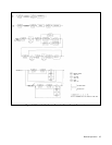
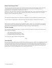
Status Reporting
The power supply has the ability to report its internal status to the user whenever it is asked to do so. Depending on the type
of status the user requested, the supply will interrogate the status, accumulated status, mask, or fault registers present in
each output. The status register can report status independently or it can work together with the mask and fault registers to
report a fault. The accumulated status register records every status condition the output experienced since the time it was
last read. Figure 5-3 shows a conceptual model of the operation of these registers.