


Getting Started32
If you have any questions concerning installation or power requirements, review Chapter 2.
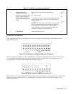
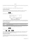
To turn on your supply, press the front panel LINE switch. When the power is initially applied, the supply performs a series
of self tests which last about 3 seconds. Included in these tests are checks of circuits on the GP-IB board and on each of the
output boards.
SYSTEM OUTPUT ENTRY
LINE
ON
OFF
LCL
ADDR
ERR
STO
RCL
METER
DLY
FAULT
UN
MASK
OCP
OUTPUT
SELECT
VSET
ISET
OUTPUT
ON/OFF
ENTER
789
456
123
0.
6624A SYSTEM DC POWER SUPPLY
1 2 3 4 CV CC UNR OCP ERR RMT ADDR SRQ
ENBLD-- OUTPUT --
5.15V 2.35A
OV
SET
OV
RST
OC
RST
9 4 2
87613 5
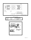
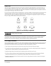
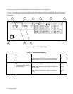
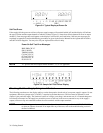
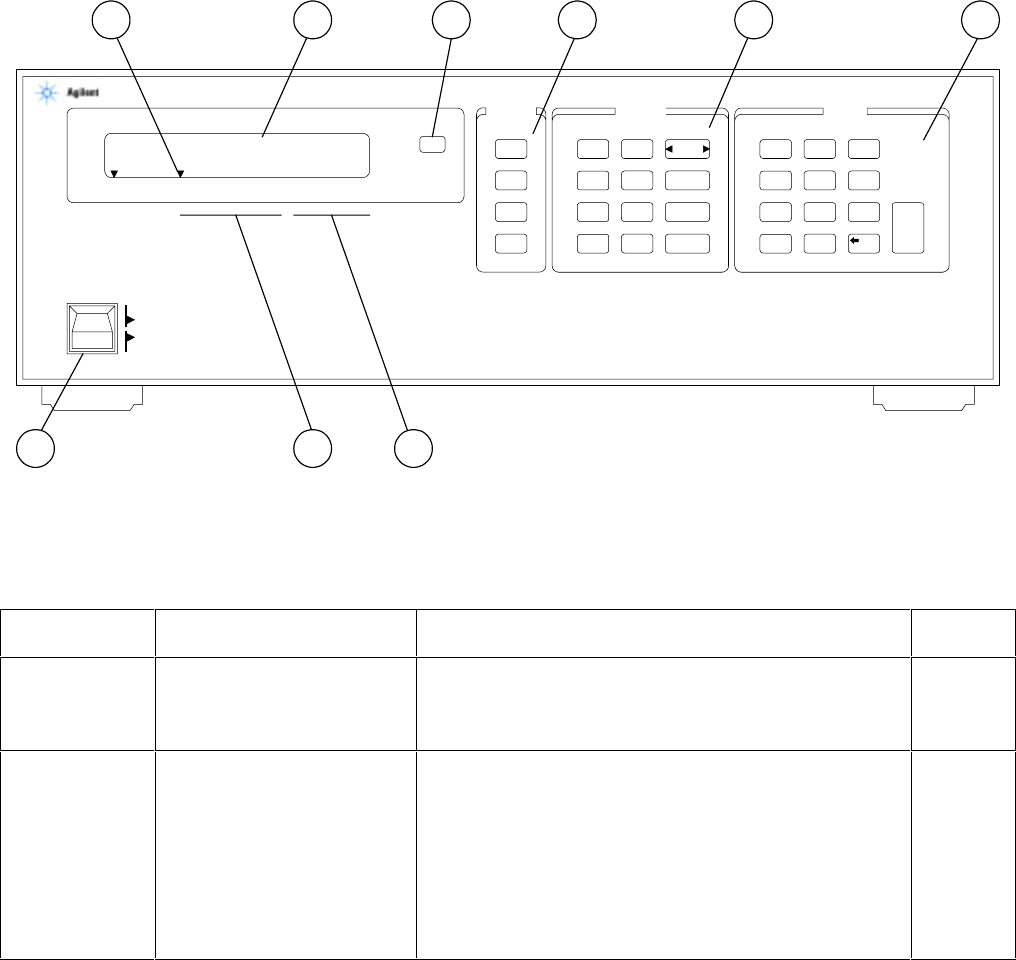
Figure 3-1. Agilent 6624A Front Panel
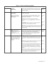
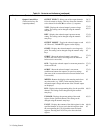
Table 3-1. Controls and Indicators
Number
Controls/lndicators
Description
Page
1
LCL key
Returns power supply to local mode (unless local lockout
has been received via GP-IB). Also, turns the power
supply’s display on if it was turned off via the GP-IB.
39, 61,
83
2
GP-IB Status Annunciators
(These three annunciators
indicate the GP-IB status of
the power supply) .
RMT - Indicates that the power supply is operating under
remote control (GP-IB).
ADDR - Indicates that the power supply is addressed to
talk or to listen.
SRQ - Indicates that the power supply is requesting
service.
39, 61,
83
37, 61
61, 61,
68