General Information14
The power supply has no potentiometers. Each output is individually calibrated over the GP-IB using calibration commands
(see Appendix A). Correction factors are calculated by the power supply during calibration and are stored in a non-volatile
memory which is located on the supply’s GP-IB board. The supply contains no batteries.
Output Boards
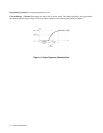
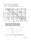
The output boards are linear dc power supplies. Each isolated output has the L-shaped operating curve described in
Description, page 12 and Figure 1-1.
The ac input to each output board is rectified and applied to a regulator circuit. Each output board employs series regulation
techniques. A regulator element is connected in series with the load and operates in the linear region (between saturation
and cutoff) of the transistor characteristic curve. Regulation is achieved by varying the conduction of the series element in
response to a change in line voltage or circuit load.
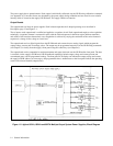
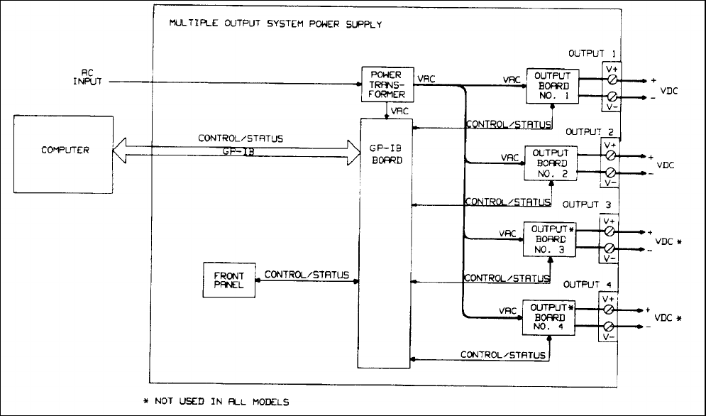
The output board receives digital signals from the GP-IB board and converts them to analog signals which program the
output voltage, current, and overvoltage values. The output may be programmed remotely over the GP-IB using commands
(see Chapter 5) or locally from the supply’s front panel using the control keys (see Chapter 6).
The output board can be commanded to send measurement and status data back over the GP-IB and/or front panel. The data
is sent back via the supply’s GP-IB board. GP-IB readback capabilities include output voltage and current, present and
accumulated status, and all programmed settings. The front panel LCD display can indicate the output voltage and current,
the supply’s GP-IB address, error messages, and programmed values. Annunciators on the front panel indicate the operating
status of the selected channel (output board).
Figure 1-2. Agilent 6621A, 6624A and 6627A Multiple Output System Power Supplies, Block Diagram


