General Information 19
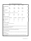
Table 1-3. Supplemental Characteristics (continued)
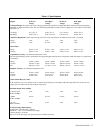
Outputs 40 W Low 40 W High 80 W Low 80 W High
Voltage Voltage Voltage Voltage
Programming Resolution:
Voltage 6 mV 15 mV 6 mV 15 mV
+Current 25 mA 10 mA 50 mA 20 mA
OVP 100 mV 250 mV 100 mV 250 mV
Readback Resolution:
Voltage 6 mV 15 mV 6 mV 15 mV
+ or-Current 2 mA 0.8 mA 4 mA 1.6 mA
Fixed Overvoltage Protection: (Measure at output terminals +V and -V):
Minimum 22.5 V 56 V 22.5 V 56 V
Nominal 24 V 60 V 24 V 60 V
Maximum 26 V 64 V 26 V 64 V
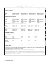
AC Input Power and Current:
Maximum Power = 550 W
100 V Option 120 V Option 220 V Option 240 V Option
High Line Inrush Current
(pk)
85 A 85 A 50 A 50 A
High Line Input Current
(rms)
6.3 A 5.7 A 3.0 A 3.0 A
Fuse Rating 8 A 8 A 4 A 4 A
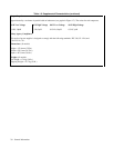
GP-IB Interface Capabilities:
SH1, AH1, T6, L4, SR1, RL1, PP1, DC1, DT0, C0, E1
Current Sink Capability:
Current sink limits are fixed approximately 10% higher than the maximum current source limits for a given operating
voltage at any voltage above 2.5 V (see Chapter 4).
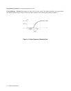
Command Processing Time: (see Figure 1-3):
7 milliseconds typical (with front panel display disabled). Using STO and RCL commands allows you to change all the
voltage and current settings in about 10 mS (with front panel display disabled).
Series and Parallel Operation:
Two outputs can be operated directly in parallel or can be connected for straight series operation. Refer to Chapter 4 for
more information.
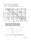
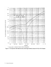
Reactive Load Capability:
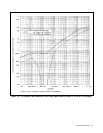
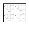
All outputs have been designed with the ability to operate with significant reactive loads without instability (refer to
Figures 1-4 through 1-6).


