Calibration Procedures92
Start with output channel 1 and use the following commands to calibrate your power supply:
NOTE Do not turn the power supply off during the calibration procedures. Otherwise, the correction constants
are not stored. Exercise care when moving the leads.
1. CMODE < param > - This command turns the calibration mode either on or off. The parameter must be either a 1
or a 0. CMODE1 is used in the beginning of the calibration procedure to turn calibration mode on. CMODE must
be on to use any of the calibration statements. CMODE0 is used at the end of the procedure to store the correction
constants and turn calibration mode off. The CMODE? query can also be used at any time to determine if the
supply is in calibration mode. A 1 indicates calibration mode is on; a 0 indicates calibration mode is off. Continue
to the next command.
2. VHl<channel> - This command causes the voltage of the specified output channel to go to the high calibration
point (full scale). After the command is sent, use the voltmeter to read the actual voltage <Vhi > put out by the
power supply. Continue to the next command.
3. VLO < channel > - This command causes the voltage of the specified output channel to go to the low calibration
point (voltage offset). After the command is sent, use the voltmeter to read the actual voltage < Vlo > put out by
the power supply. Continue to the next command.
4. VDATA < channel >, < Vlo >, < Vhi > - This command is used to send the actual values measured by the
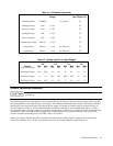
voltmeter in the previous steps to the power supply. Refer to Table A-2 for the range of valid voltage readings that
can be sent to the supply. <Vlo> is the voltage in volts that was measured after the VLO command was sent. < Vhi
> is the voltage in volts that was measured after the VHI command was sent. The power supply uses these values
to calculate the voltage and voltage readback correction constants of the specified output. Continue to the next
command.
5. OVCAL < channel > - This command automatically calibrates the programmable overvoltage. This can only be
done after the voltage has been calibrated. It may take up to 10 seconds for this command to execute. During this
time, the front panel display indicates "CALIBRATING" .
When the front panel display of the power supply no longer indicates ’’CALIBRATING", the overvoltage portion of the
calibration procedure is complete. The voltages on the output are returned to zero volts after the overvoltage calibration. To
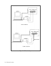
continue with the current portion of the calibration procedure, connect a four terminal 0.1
Ω
current shunt resistor (0.05%,
10 A) between the +V and -V output terminals. Connect the voltmeter to the resistor’s sense terminals. Refer to the current
calibration setup in Figure A-1.
Continue calibrating output 1 with the following commands:
6. IHI < channel > - This command causes the current of the specified output channel to go to the high calibration
point (full scale). After the command is sent, use the voltmeter to read the voltage drop across the current shunt
resistor. Divide this reading by the shunt value to derive the actual current in amps < Ihi > put out by the supply.
Continue to the next command.
7. ILO <channel> - This command causes the current of the specified output channel to go to the low calibration
point (current offset). After the command is sent, use the voltmeter to read the voltage drop across the current
shunt resistor. Divide this reading by the shunt value to derive the actual current in amps <Ilo> put out by the
supply. Continue to the next command.
8. IDATA < channel >, < IIO >, < Ihi > - This command is used to send the actual current values derived in steps 6
and 7 to the power supply. Refer to Table A-2 for the range of valid current readings that can be sent to the supply.
< Ilo > is the current in amps that was put out by the supply after the ILO command was sent. < Ihi > is the current
in amps that was put out by the supply after the IHI command was sent. The power supply uses these values to
calculate the current and current readback correction constants of the specified output.


