


Output Connections and Operating Information 54
Power Supply Protection Considerations
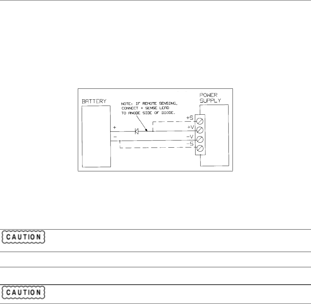
Battery Charging
If you are using your supply in a battery charging application, it is recommended that a series protection diode be added to
prevent damage to the supply during an overvoltage shutdown. Remember that each output has an overvoltage protection
circuit that fires a crowbar to disable the output for any of the OVERVOLTAGE conditions described in Protection
Features, page 44.
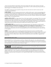
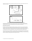
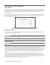
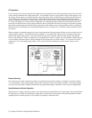
Figure 4-10 illustrates the recommended connections and protection circuit for a battery charging application. The diode
will prevent damage to your supply that can result from excessive battery current flowing into the supply’s output in the
event of an overvoltage shutdown.
Figure 4-10. Recommended Protection Circuit for Battery Charging
Capacitive Load Limitation
The programmable overvoltage protection circuit can be used to downprogram capacitive loads although it is primarily
intended for use as a protection feature (page 44).
Repetitive (over 100 cycles) tripping of the overvoltage circuit with output capacitors greater than
5000
µ
F on high voltage units and 20,000
µ
F on low voltage units may result in eventual damage to the
supply.
Parallel Operation
Connect in parallel only outputs that have equivalent voltage and current ratings.
Connecting outputs in parallel provides a greater current capability than can be obtained from a single output. Because each
output contains an active downprogrammer that is capable of sinking current from only ONE identical output, you can
parallel no more than two outputs. These outputs must have equivalent voltage and current capability. For example, you can
connect the 40 W low voltage outputs together because they have the same voltage and current ratings, but you cannot
connect a 40 W high voltage and a 40 W low voltage output together because they have different voltage and current
ratings.
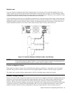
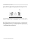
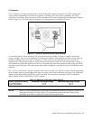
As an example, Figure 4-11 shows how to connect two outputs in parallel to a single load with local sensing. This
configuration applies to both CV and CC operating modes. Connecting the load leads of output 2 directly to the + V and
- V terminals of output 1 keeps the total length of the load leads to a minimum and reduces the number of wire connections
that must be made at the load itself. Connecting the + S and - S terminals of output 2 directly to the sense terminals of
output 1 compensates for the IR drop in the interconnecting load leads.