


Multimode Source for 6100 Series Single Quad LC/MS Set-Up Guide 9
Installation 1
Step 2. Install the HV control PCA and cables
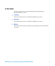
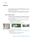
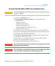
• Valve BD-APCI supply, p/nG1960-60802
• Valve BD-APCI Needle Interlock, p/n G1960-60856
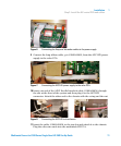
Figure 2 From left to right: G1946-80058, G1960-60802 and G1960-60856
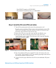
Step 2. Install the HV control PCA and cables
1 Turn off the system power and remove the system power cord.
Keep the power cord intact if the vacuum control switch box is used. The
switch box is intended to keep the vacuum on while a CE works on the
electronics. The switch box is for CE use only.
2 Remove the CDS cover, top, side, front, and the Aux Module cover.
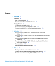
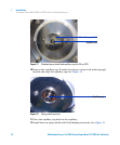
3 Disconnect the ribbon cable that connects the valve PCA to the
Vcap/Vchamber power supply. Then disconnect the Vcap and Vchamber
cable from the power supply.
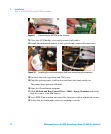
Figure 3 Disconnecting the Vcap/Vchamber power supply from the valve PCA (left) and the Vcap/Vchamber.
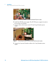
4 Place the multimode HV power supply PCA in the slot between the valve
PCA and the Vcap/Vchamber. Secure the board by pressing it down into its
slot and then attach it with two screws.
5 Connect the short gray cable from valve PCA to the multimode HV power
supply.