


MULTITASKER
400-0367-005 7
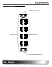
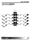
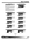
INSTALLING YOUR MT107-103 6
Step 1. Determine the number of slots required
for the MT107-103, including the add-on
cards. The base MT107-103 requires two
slots, and a fully loaded 64X64 Matrix
Engine requires 16 slots.
Step 2. Turn off power to the MultiTasker system
and disconnect from AC power.
Step 3. Carefully, slide the MT107-103 into
available slots in the MultiTasker
enclosure in order to connect to the bus.
Make sure that the MT107-103 cards fit
into place.
Step 4. Secure the cards to the MultiTasker by
tightening the retainer screws located on
the top and bottom of each card.
Step 5. Connect a cable from an audio source to
one of the input connectors on the
MT107-103 and another cable from an
output connector to a receiving device.
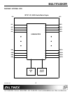
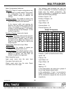
Step 6. Starting from the left, identify the slot
number where the MT107-103’s Input
Connector Card is plugged into the
enclosure.
The Input Connector Card is the circuit
card on the left-hand side of the engine
as it is being installed. Make note of the
slot number. It is required for RS-232
control.
Step 7. Restore power to the MultiTasker system.
Step 8. The MT107-103 is now operational.
OPERATION 7
7.1 RS-232 CONTROL
The MT107-103 has many advanced
remote-control capabilities accessible through
standard RS-232 communication. Control may be
accomplished through a computer, control system,
or any device capable of RS-232 communication.
7.1.1 RS-232 INTERFACE
The control commands for the MT107-103 are
in a simple ASCII character format.
1. Square brackets “[ ]” are part of the
command.
2. Use uppercase letters for all commands.
3. Spaces are not legal characters.
The cards in a MultiTasker are capable of
performing various functions, as well as
providing feedback to the user or control
system. Commands instruct a card to perform
specific actions or request information from the
card. Some commands do both simultaneously.
A command that instructs the card only to
perform an action will generate feedback of “[ ]”.
The open bracket immediately followed by a
closed bracket indicates the card received a
valid command. If the command requested
information from the card, the feedback
generated by the card is the acknowledgement
of having received a valid command. Invalid
commands generate feedback that includes
“ERR” plus an error code.
Example: [ERR001]
After processing a command, an “OK” or error
will be returned as feedback if “F” is included at
the end of a command string.
Commands ending in “S” will be saved into
memory. Commands not ending in “S” will still
be executed, but will not be restored when the
system is reset or powered off, then on.