


MX28B1200/2400 MX28B1200/4800 –48 VDC User’s Manual Page 20
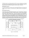
Bolt-in Circuit Breaker Installation
1) Remove the circuit breaker cover panel and the plastic cover(s) from the desired location(s).
2) Install the circuit breaker(s) by bolting the circuit breaker onto the bus at the bottom of the
assembly. Bolt the lug landing bus to the top of the breaker.
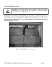
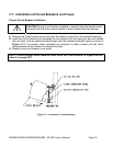
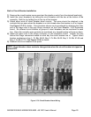
3) Attach alarm wires to circuit breaker alarm outputs. The wires should be attached to the
contacts that are open when the breaker is on and closed when the breaker is off or tripped.
See Figure 3.7-2 for details. Circuit breaker alarms can be monitored by attaching the other
end of the alarm wire to the gray Wago connector on the Circuit Breaker / LVD Expansion
board. Six different circuit breaker or groups of circuit breakers can be monitored in each
bay. Since the normally open contacts are monitored, any tripped breaker will give an alarm.
4) Install the alarm wire in the Wago connector on the expansion board. Jumper the pins
behind the Wago connectors based on what bay the circuit breaker are in. Typical circuit
breaker numbering is bay 1: Cir Bkr 49-54, Bay 2: Cir Bkr 55-60, Bay 3: Cir Bkr 61-66 and
Bay 4: Cir Bkr 67-72. See Figure 3.2-6 for details.
5) Reattach the circuit breaker cover panel.
NOTE: Circuit breaker alarm contacts change state when the circuit breaker is tripped or
turned OFF.
Figure 3.7-2 Circuit Breaker Alarm Wiring