


MX28B1200/2400 MX28B1200/4800 –48 VDC User’s Manual Page 28
b. Case leaks.
c. Post- seal leaks.
d. Pressure relief valve leaks (VRLA only).
e. Case swelling (VRLA only).
f. Case swelling (VRLA only).
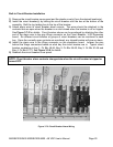
10. Check the torque of all battery inter- cell connector in accordance with the battery
manufacturer’s specifications.
4.2. Commissioning
Initial Set-up
1. Remove all rectifiers. Ensure that the float/equalise switch is on float.
2. Disconnect battery by removing a link in each string or opening the battery disconnects.
3. Check that battery voltage does not appear on the system bus.
4. Disconnect all loads.
AC Power Up
WARNING: The DC power plant is supplied from a nominal high voltage AC
voltage source. Keep the AC input enclosure cover in place when the system
is operational or energized
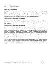
1. Verify that AC voltage is present for each rectifier at the back- plane position (Blue J2 of
0P-9131) inside the rectifier compartment. The AC input breaker for each rectifier should
be switched on and off to ensure that you have power at every rectifier and that the
breaker disconnects the rectifier.
2. Verify that all of the circuit breaker positions are labeled to the corresponding rectifier
correctly.
3. Insert all rectifiers.
4. Turn all rectifier circuit breakers on.
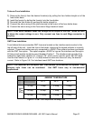
5. The main screen should appear on the control unit display (see Figure 5.6-1). The
display on the control unit is a 2-lines by 16-characters display. The cursor cycles below
the characters of the active selection on the display. Information shown in the second
line of Figure 5.6-1 that extends beyond 16 characters (to the right of the “S” in
“ALARMS”) can viewed on the control unit display by using the scrolling controls (refer to
Section 5.6 for operation of the control unit).
NOTE: When AC power is initially applied, there is a 60-second period during which no alarms
are reported.