


MX28B1200/2400 MX28B1200/4800 –48 VDC User’s Manual Page 10
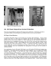
input. The AC wiring, from the AC input terminal block connections to the hot-pluggable AC
input connector for each rectifier, is factory installed.
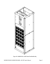
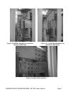
The AC input enclosure, located at the top rear of the MX28B rectifier bay, is provided with nine
¼ -inch pilot holes in the top plate. Remove the ac input enclosure from the box frame in order
to punch or drill the appropriate number of conduit openings for the conduit size(s) desired. Do
not leave the ac input enclosure in place when punching or drilling holes in order to prevent
metal pieces from falling into the power system.
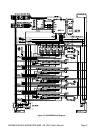
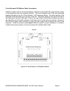
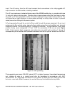
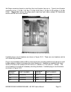
AC wiring passing through the conduit will be routed through the access opening in the ac input
enclosure into the vertical wiring channel where safety ground bar and rectifier input terminal
blocks are located. The terminal block(s) is labeled as Rectifier 1 through Rectifier 4 with each
position having inputs designated “L1” and “L2/N” for connection of the two ac wires Figure
3.3-1. Each terminal block represents connections for one shelf, with positions 1 through 4
corresponding to the rectifier shelf positions numbered from left to right as viewed from the front.
Figure 3.3-1 AC Input Wiring
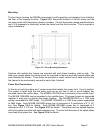
The suggested wire size is #10 AWG rated at 90°C or higher; however, the ambient temperature
and number of wires in a conduit must also be considered in accordance with NEC
requirements. It is suggested that feeds for four rectifiers (8 wires) and one safety ground wire
be run in a one-inch conduit; however, be sure to follow any local electrical wiring codes.