


MX28B1200/2400 MX28B1200/4800 –48 VDC User’s Manual Page 21
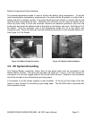
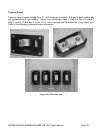
Telecom Fuse Installation
1) Remove the fuse(s) from the desired location(s) by pulling the fuse holder straight out of the
fuse holder base.
2) Install the fuse(s) by bolting the fuses(s) into the fuse holder.
3) Re-install the fuse holder by pushing the holder straight in.
4) Connect the alarm wiring to the alarm terminal at the output of the fuse holder base.
5) Connect the alarm wiring to the Fuse alarm Wago breakout board.
NOTE: Fuse alarm contacts sense the voltage on the output of the fuse. When the fuse
is blown the output voltage is zero. Only connect one fuse to each Wago connector in
any bay.
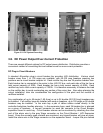
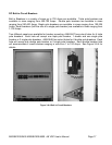
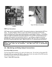
GMT Fuse Installation
Fuse holders that accommodate GMT fuses are located on the interface card mounted in the
top left side of the unit. Insert the fuse in the holder; observing the tripped indicator is correctly
oriented. These fuse holders are only connected to -48VDC if the system has been purchased
with the GMT fuse option. This option supplies -48VDC to lugs on the interface card through a
50 Amp circuit breaker located in circuit breaker Position 1. The interface card provides fuse
holders for eight fuses, labeled “F1” through “F8”, which can be used for small -48V DC loads.
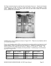
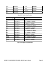
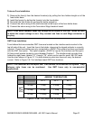
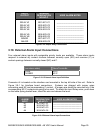
Use the chart shown in Figure 3.7-3 to help determine what size fuses will carry the desired
current. Refer to Figure 3.9-1 for Interface board GMT fuse locations.
NOTE: The controller will not report GMT Fuse failures in the MX28B1200 system. Only
telecom style fuses can be monitored. Use GMT fuses only in non-essential
applications.
AMBIENT TEMPERATURE
20° C 50° C 60° C
10 Amp 7 Amp 6 Amp 5 Amp
12 Amp 8 Amp 7 Amp 6 Amp
FUSE
SIZE
15 Amp 10 Amp 9 Amp 8 Amp
Figure 3.7-3 GMT Fuse Temperature De-rating Chart