


MX28B1200/2400 MX28B1200/4800 –48 VDC User’s Manual Page 8
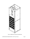
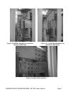
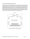
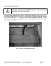
Circuit Breaker/LVD Ribbon Cable Connections
Additional cables must be connected between cabinets to ensure that the circuit breaker alarms
in the expansion bays are reported correctly. The circuit breakers and LVDs are connected
together through the use of a Circuit Breaker / LVD Expansion Board. The ribbon cables on the
left hand side of the board go to the bay to the left. The ribbon cables on the right hand side of
the board go to the bay to the right. If there is an open Alarm Contact Bus connector (no bay to
the side of the unit) the cable connector is left open and no further action is required. However if
the LVD Bus ribbon cable connector is open, the pins nearest the connector will have to be
jumpered. Install the jumpers using Figure 3.2-5 as a guide to jumper orientation. If a cable is
installed remove the jumpers on the pins nearest the installed ribbon cable.
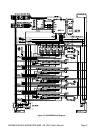
Figure 3.2-5 Circuit Breaker / LVD Expansion Board