


MX28B1200/2400 MX28B1200/4800 –48 VDC User’s Manual Page 36
right corner of the display. If a security level higher than the one presently set is required to
modify the parameter, "s+" is displayed instead of “m+”. Status, alarms, and information
screens have "+" in the upper right corner of the display (or “#” in the case of rectifier information
screens) and cannot be modified. When AC power is initially applied, there is a 60-second
period during which no alarms are reported.
Pressing the "M" key on the front panel will change the "m+" to "M+", indicating that the
parameter can now be changed using the arrow keys. Some parameters can be changed to
other predefined selections by pressing the up or down arrow keys to display an alternative
selection. These parameters can be recognized after the “M” key is pressed by the cursor
cycling beneath the characters of the selection. For other parameters, such as text and most
numeric values, after the “M” key is pressed the cursor will be displayed under an individual
character. The right or left arrow key is used to position the cursor below the character to be
changed and the up or down arrow key is used to "spin" the digit or letter to the desired value.
When the desired changes have been made to an individual parameter screen, the “M” key is
pressed again; the “M+” changes back to “m+” and the new entry is stored in memory.
If the user plans to make any changes to system parameters, the first item that should be
verified or entered is the appropriate password for the security level required for the parameters
to be modified. Security level 2 (enter 2222 on the “PIN” screen) enables modification of all
variable system parameters. Security level 1 (enter 1111 on the “PIN” screen) permits
modification of some parameters. No security is required for viewing status items and
parameter settings. The security level password is entered through the “PIN” screen. If no front
panel keys are pressed for 60 minutes, the active security level password reverts to level 0 and
“█APC█” begins to move about the display. Pressing any key returns the display to normal and
the password must be re-entered if system parameters require changes.
Eleven LEDs are provided on the front panel of the control unit to indicate system status. Three
LEDs grouped together vertically provide overall system status; they are “MAJOR”, “MINOR”,
and “NORMAL”, indicating the presence of a major alarm, a minor alarm, or normal operation.
The other eight LEDs correspond to the active state of each of the alarm output relays and are
labeled “ALM1”∙∙∙“ALM6”, “MIN”, and “MAJ”.
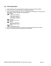
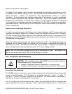
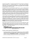
MX28B-1200 +
STATUS ALARMS SYSTEM MODULES BATT PIN OEM
Figure 5.6-1 Menu Top Line
.
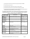
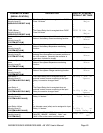
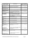
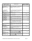
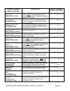
Parameter Locations, Descriptions, and Default Values
The location, description, and factory programmed default value for each of the MX28B
system parameters is found in the table below. The table also shows all of the status and
information screens with typical displays. The location of a parameter screen is shown in
brackets, for example: [SYSTEM/IN-RLY/RLY-MAP]. To find the parameters that can be
accessed in this category, starting from the main menu screen, do the following: