


MX28B1200/2400 MX28B1200/4800 –48 VDC User’s Manual Page 52
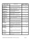
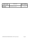
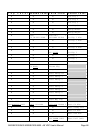
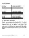
Front Panel LED Indicators
Major (Red) On when Major Relay is de-energized*
Minor (Yellow) On when Minor Relay is energized
Normal (Green) On when no alarms are active
ALM 1 (Red) On when Output Relay 1 is energized
ALM 2 (Red) On when Output Relay 2 is energized
ALM 3 (Red) On when Output Relay 3 is energized
ALM 4 (Red) On when Output Relay 4 is energized
ALM 5 (Red) On when Output Relay 5 is energized
ALM 6 (Red) On when Output Relay 6 is energized
MIN (Red) On when Minor Relay is energized
MAJ (Red) On when Major Relay is de-energized*
* This will produce a major relay output even when all power is lost.
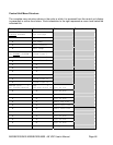
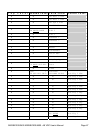
5.7. Alarm Outputs (Output Relays)
There are eight alarm output relays designated Relay 1 through Relay 6, Minor, and Major,
respectively. Various system parameters may be programmed to activate any of these alarm
relays when set thresholds are exceeded or specific conditions occur. The first six relays can
also be assigned a priority and routed or “mapped” to other output alarm relays. Available
assignments are “Ignore”, “Major”, “Minor”, and “Relay 1” ··· “Relay 6”. Screens for making
these assignments are located at [SYSTEM/OUT-RLY/RLY-MAP]. This feature makes it
possible for a single alarm condition to activate multiple alarm output relays including the Minor
or Major alarm relay. A user defined name or “alias” may also be assigned to each of the eight
output relay alarms. Screens for making these assignments are located at [SYSTEM/OUT-
RLY/ALIAS]. For information on making wiring connections to the alarm output relays refer to
Section 3.9