


Chapter 2 Product Overview
MightyBoard 821 Reference Manual 7
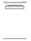
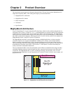
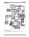
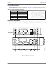
Block Diagram
Figure 2-2 shows the functional components of the MightyBoard 821.
Figure 2-2. Functional Block Diagram
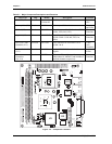
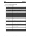
Major Components (ICs)
Table 2-1 lists the major integrated circuits (chips), including a brief description of each, on the
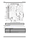
MightyBoard 821 and Figure 2-3 shows the location of the major chips.
MB821Blkdi
agm_b
Intel
Pentium M
or Celeron M
CPU
DDR2
SODIMM
Memory Bus
Magnetics-
RJ45
Keyboard/
Mouse
SMBus
PCIe Bus
Connector
PCIe
x16 Bus
PCIe
x1 Bus
IrDA 1.1
Parallel
AC’97
CODEC
COM3
COM4
USB Port 2
USB Port 1
USB Port 0
USB 2.0
Super I/O
W83627HF
COM1
COM2
AC’97 Link
Clock
Temp
512kB
ROM
BIOS
Ethernet
Controller(2)
82573V
CRT VGA
LVDS LCD
Magnetics-
RJ45
GPIO (User Defined)
Memory Hub
82915GM
(Northbridge)
I/O Hub
82801FB
(Southbridge)
SATA
IDE
PATA
SATA
IDE Devices,
(HDDs,
)
CD-ROM, etc.
RS232/RS422/RS485
LPC Bus
LPC I/O
(Secondary)
F81216D
CPU Fan
USB Port 3
USB Port 4
USB Port 5