


Chapter 2 Product Overview
10 Reference Manual MightyBoard 821
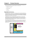
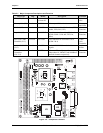
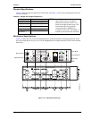
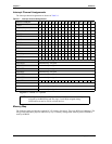
Figure 2-4. Connector and Header Locations
Additional Components
Fuses F1 and F2, in Table 2-3, are shown in Figure 2-4. Fuses F3 and F4 can be found on the back of the
board.
NOTE Pin-1 is shown as a black pin (square or round) in all connectors and jumpers in
all illustrations.
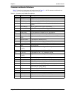
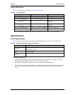
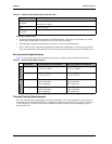
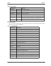
Table 2-3. Additional Component Descriptions
Component Description
F1 (1.6A) Auto Reset Overcurrent Fuse for the USB 4 & 5 (J21)
F2 (1.6A) Auto Reset Overcurrent Fuse for the USB 0 & 1 (J11)
F3 (1.1A) Auto Reset Overcurrent Fuse for the Keyboard/Mouse (J1)
F4 (1.6A) Auto Reset Overcurrent Fuse for the USB 2 & 3 (J13)
J4
J3
J5
J20
J22
BT1
J1
JP1
F2
F1
DIMM2
DIMM1
J16
J15
JP6
J21
J17
J18
J2
J6
J8
J9