


Chapter 3 Hardware
28 Reference Manual MightyBoard 821
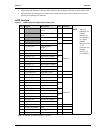
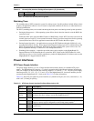
Note: The shaded area denotes power or ground.
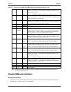
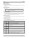
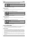
Optional CPU Fan
The MightyBoard 821 has an optional CPU fan connector for those environmental situations where
customers may require it.
Note: The shaded area denotes power or ground.
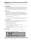
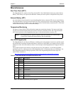
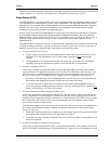
Optional System Fan
The MightyBoard 821 has an optional system fan connector for those environmental situations where
customers may require it.
Note: The shaded area denotes power or ground.
Power and Sleep States
The following information only applies to the MightyBoard 821, if an ATX power supply is used to provide
power. If a non-ATX power supply is used, then the MightyBoard 821 is only controlled by the
Power-On/Off switch on the power supply and the various sleep states are not available.
Power-On Switch
The Power-On switch turns the MightyBoard 821 and its attached power supply to a fully On condition, if
you are using an ATX power supply. Normally, if the operating system (OS) supports sleep states, the OS
will turn off the MightyBoard 821 and its power supply during the OS shut down process. If the OS supports
sleep states, the Power-On button will also transition the MightyBoard 821 and its power supply between a
fully Powered On state, various sleep states depending on the OS control setting, and a fully Powered Off
state. If the OS does not support sleep states, then the Power-On button only turns power on or off to the
MightyBoard 821.
The sleep states are OS dependent and not available if your OS does not support power management based
on the ACPI standard. An OS supporting ACPI will allow the Power-On button to be configured through a
user interface.
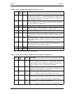
13, 15
GND Ground line
14 PS-On Power Supply On – This signal turns on and off the ATX power supply.
16, 17
GND Ground line
18 NC Not connected (-5.0 volts)
Table 3-13. Optional CPU Fan Interface Pin/Signal Descriptions (J12)
Pin # Signal Description
1 DET Fan Speed Detect – This is the fan speed tachometer signal.
2
+12 +12 volts DC +/- 5%
3
GND Ground
Table 3-14. Optional System Fan Interface Pin/Signal Descriptions (J22)
Pin # Signal Description
1 DET Fan Speed Detect – This is the fan speed tachometer signal.
2
+12 +12 volts DC +/- 5%
3
GND Ground
Table 3-12. ATX Power Supply Interface Pin/Signal Descriptions (J2) (Continued)