


Chapter 3 Hardware
MightyBoard 821 Reference Manual 27
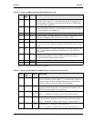
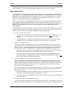
Note: The shaded area denotes power or ground.
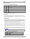
Watchdog Timer
The watchdog timer (WDT) restarts the system if a mishap occurs. Possible problems include failure to boot
properly, the application software’s loss of control, unexpected conditions on the bus, or other hardware or
software malfunctions.
The WDT (watchdog timer) can be used both during the boot process and during normal system operation.
• During the Boot process – If the operating system fails to boot in the time interval set in the BIOS, the
system will reset.
Enable the WDT in the Advanced BIOS Features of BIOS Setup. Set the WDT for a time-out interval in
seconds, between 2 and 255, in one second increments. Ensure you allow enough time for the operating
system (OS) to boot. The OS or application must tickle the WDT before the timer expires.
• During System Operation – An application can set up the WDT hardware through a BIOS call, or by
accessing the hardware directly. Some Ampro Board Support Packages provide an API interface to the
WDT. The application must tickle the WDT before the timer expires or the system will be reset. The
BIOS implements interrupt 15 function 0C3h to manipulate the WDT.
• Watchdog Code examples – Ampro has provided source code examples on the MightyBoard 821
Support Software DVD illustrating how to control the WDT. (Refer to the WDT Readme file in the
Miscellaneous Source Code Examples subdirectory, under the MightyBoard 821 Software menu on the
MightyBoard 821 Support Software DVD.)
Power Interfaces
ATX Power Supply Interface
The power supply interface, J2, uses a 20-pin interface that connects directly to a standard ATX power
supply. The MightyBoard 821 requires +12 volts for operation and all the onboard voltages, including the
CPU core voltages, are derived from the externally supplied +12 volts DC +/- 5%. The ATX power supply
interface provides -5V, -12V, +5V, +3.3V and +12V to the MightyBoard 821, but not all interface pins are
connected at the MightyBoard 821. Refer to the Table 3-12 for more information.
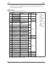
Table 3-12 shows the pin signals for power interface (J2), which has 20-pins, two rows, consecutive (1, 11)
with 0.165" (4.2mm) pin spacing.
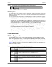
4 IRRX IR Receive Data
5
GND Ground
Table 3-12. ATX Power Supply Interface Pin/Signal Descriptions (J2)
Pin # Signal Description
1, 2, 11
+3.3 +3.3 volts – This voltage used for PCI bus.
3, 5, 7
GND Ground
4, 6,
19, 20
+5V +5 volts +/- 5% – This is the main input voltage to the MightyBoard and it
generates the other voltages used on the MightyBoard 821.
8 NC Not connected (Power Ok or Good)
9
5VSB +5V, 100mA Standby voltage – Input to MightyBoard from ATX type power
supply to power specific components on the board during standby.
10
+12V +12 volts +/- 5% – This provides voltage to the CPU Fan, LCD backlite supply
and PCI bus.
12
-12V -12 volts – This voltage goes to PCI bus only
Table 3-11. Infrared (IrDA) Interface Pin/Signal Descriptions (J7) (Continued)