


Contents
iv Reference Manual MightyBoard 821
Infrared (IrDA) Port .................................................................................................................. 26
Watchdog Timer....................................................................................................................... 27
Power Interfaces .......................................................................................................................... 27
ATX Power Supply Interface ................................................................................................... 27
Optional CPU Fan....................................................................................................................28
Optional System Fan ...............................................................................................................28
Power and Sleep States................................................................................................................ 28
Power-On Switch .................................................................................................................... 28
Sleep States (ACPI)................................................................................................................. 29
Chapter 4 BIOS Setup..............................................................................................................31
Introduction.................................................................................................................................... 31
Entering BIOS Setup (VGA Display)........................................................................................ 31
Entering BIOS Setup (Remote Access) .................................................................................. 31
Logo screen ..................................................................................................................................32
Logo Screen Image Requirements .......................................................................................... 32
Appendix A Technical Support .................................................................................................. 33
List of Figures
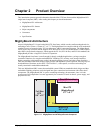
Figure 2-1. MightyBoard and ATX Style Boards Compared ...................................................... 3
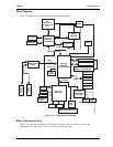
Figure 2-2. Functional Block Diagram ....................................................................................... 7
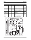
Figure 2-3. Component Locations ............................................................................................ 8
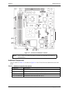
Figure 2-4. Connector and Header Locations .........................................................................10
Figure 2-5. Back Panel Overview ............................................................................................13
Figure 3-1. RS485 Serial Port Implementation ........................................................................18
List of Tables
Table 2-1. Major Component Descriptions and Functions .......................................................8
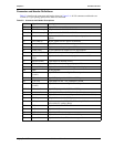
Table 2-2. Connector and Header Descriptions ....................................................................... 9
Table 2-3. Additional Component Descriptions ...................................................................... 10
Table 2-4. Jumper Settings .................................................................................................... 11
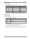
Table 2-5. System Power Requirements (1.5 GHz CPU).......................................................11
Table 2-6. System Power Requirements (2.0 GHz CPU).......................................................12
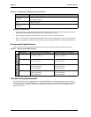
Table 2-7. Environmental Requirements................................................................................ 12
Table 2-8. Weight and Footprint Dimensions ......................................................................... 13
Table 3-1. Interrupt Channel Assignments.............................................................................16
Table 3-2. Memory Map ......................................................................................................... 17
Table 3-3. I/O Address Map ................................................................................................... 17
Table 3-4. Serial 2 (COM2) Interface Pin/Signal Descriptions (J6) ........................................ 19
Table 3-5. Serial 3 and 4 (COM3 and COM4) Interface Pin/Signal Descriptions (J15)..........19
Table 3-6. USB Ports 4 & 5 Interface Pin/Signal Descriptions (J21)...................................... 21
Table 3-7. LVDS Interface Pin/Signal Descriptions (J2)......................................................... 23
Table 3-8. Utility Interface Pin/Signal Descriptions (J17) ....................................................... 24
Table 3-9. User GPIO Signals Pin/Signal Descriptions (J10).................................................25
Table 3-10. Ethernet External LED Pin/Signal Descriptions (JP6)........................................... 26
Table 3-11. Infrared (IrDA) Interface Pin/Signal Descriptions (J7) ........................................... 26
Table 3-12. ATX Power Supply Interface Pin/Signal Descriptions (J2)....................................27
Table 3-13. Optional CPU Fan Interface Pin/Signal Descriptions (J12) ................................... 28
Table 3-14. Optional System Fan Interface Pin/Signal Descriptions (J22)............................... 28
Table A-1. Technical Support Contact Information................................................................. 33