


Chapter 3 Hardware
18 Reference Manual MightyBoard 821
Serial Interfaces
The Super I/O (W83627HF) chip and the LPC UART controller (F81216D) provide the circuitry for the four
serial ports. The Super I/O chip provides serial ports 1 and 2 through connector J3 and header J6
respectively. The LPC UART controller provides serial ports 3 and 4 through header J15. The four serial
ports support the following features:
• Four individual 16550-compatible UARTs
• Programmable word length, stop bits and parity
• 16-bit programmable baud rate generator
• Interrupt generator
• Loop-back mode
• Four individual 16-bit FIFOs
• Serial Ports 1 and 2
♦
Serial Port 1 (COM1) supports RS232 and full modem support
♦
Serial Port 2 (COM2) supports RS232, full modem support, and IrDA
• Serial B Interface
♦
Serial Port 3 (COM3) supports RS232/RS485/RS422 and full modem support
♦
Serial Port 4 (COM4) supports RS232/RS485/RS422
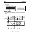
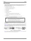
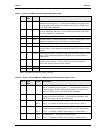
To implement the two-wire RS485 mode on serial ports 3 or 4, you must tie the equivalent pins together for
the selected port.
For example, on Serial Port 3, tie pins 3 to 5 and pins 4 to 6 at the Serial B interface connector as shown in
Figure 3-1. As an alternate, tie pins 2 to 3 and pins 7 to 8 at the DB9 serial connector for serial port 3 as
shown in Figure 3-1. Refer to the following tables for the specific pins for serial ports 3 and 4 on the serial B
connector. The RS422 mode uses a four-wire interface and does not need any pins tied together, but you
must select RS485 mode in BIOS Setup.
Figure 3-1. RS485 Serial Port Implementation
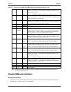
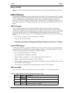
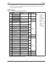
Table 3-4 lists the pin-outs for the Serial Port 2 (COM 2) interface header (J6) . Table 3-4 lists the pin-outs
for Serial Ports 3 and 4 (COM 3 and COM 4) interface header (J15).
NOTE The RS232/RS485/RS422 modes are selected in BIOS Setup under BIOS and
Hardware Settings menu for Serial ports 3 (COM3) and 4 (COM4). However,
the RS232 mode is the default (Standard) for any serial port.
RS485 mode termination is selected with jumper JP3, pins 1-2 (COM3), and pins
3-4 (COM4), when the RS485 mode is selected in BIOS Setup.
Serial B Interface (J15)
for Serial Port 3
(or COM3 Port)
1
2
3
4
5
6
7
8
9
10
20
19
Top View
5
4
32
1
9
8
7
6
Standard DB9 Serial
Port Connector (Female)
Rear View
Or
MB821_RS485