


Chapter 3 Hardware
24 Reference Manual MightyBoard 821
Utility Interface
External Power-On Switch
This control signal is provided externally through a switch by connecting ground pin 8 to pin 6 on the Utility
connector (J17).
External Reset Switch
This control signal is provided through an external switch by connecting ground pin 12 to pin 10 on the
Utility connector.
External Speaker (Beep)
The Beep signals from the I/O Hub (82801FB) and the Super I/O (W83627HF) are fed to pin 13 of the
Utility connector through an OR circuit, in conjunction with +5V (pin 7), and drives an external PC Beep
speaker. The PC Beep speaker signal from the I/O Hub (Southbridge) is also fed to the on-board Audio
CODEC (ALC202A) to provide a PC Beep signal for the Line out connections.
External Power-On LED
This indicator signal is fed to pin 1 and pin 5 of the Utility connector for an external LED to indicate power
is applied to the MightyBoard 821.
External IDE Activity LED
This indicator signal is fed to pin 2 and pin 4 of the Utility connector for an external LED to indicate power
is applied to the MightyBoard 821.
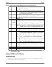
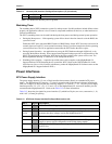
Note: The shaded area denotes power or ground.
NOTE To perform the equivalent of a power-on reset, the reset button must be pressed
and held for a minimum of three seconds.
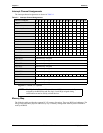
Table 3-8. Utility Interface Pin/Signal Descriptions (J17)
Pin # Signal Description
1 PwrLED Power-On LED – External Power-On LED is connected between +5 Volts
through 330 ohm resistor at pin 1, to ground at pin 5.
2, 3
VCC + 5 Voltage – Goes to +5 volts through 330-ohm resistor.
4 IDELED IDE Activity LED – External IDE Activity LED connection from Primary IDE
channel through Or circuit. Connect external Power-On LED between pin 2 (+5 V)
and pin 4 (IDE_LED).
5, 8, 12
GND Ground
6 PWRSW Power-On Switch – Connects external Power-On switch between pin 6 and ground
at pin 8.
7
VCC +5 volts – Provides +5 volts to external device (PC “Beep” speaker).
9, 11,
14, 15,
16
NC Not connected
10 RST Reset Switch – External Reset switch connection sends reset signal to Super I/O
chip. Connect external Reset Switch between pin 10 and ground, pin 12.
13 SPK PC Speaker (Beep) – Provides PC beep speaker output to external speaker. Connect
external PC Beep Speaker between pin 7 (+5V) and pin 13.