


Installation
18
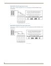
RE-DM4 and RE-DM6 RADIA Eclipse Dimmer Modules
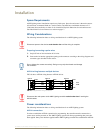
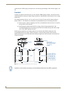
Mounting AMX Lighting Enclosures
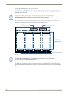
AMX Lighting enclosures must be mounted on a vertical surface with a minimum of 12" (304.8 mm)
clearance above and below the enclosure. FIG. 14 shows the centerline reference points and dimensions.
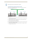
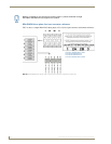
1. Remove the front cover by removing the screws at the bottom of the enclosure; two tabs suspend the
cover from the top.
2. Position the enclosure on the wall so that it is level, with the high-voltage terminals of the unit at the
top.
3. Mark the four mounting holes according to the dimensions shown in FIG. 14.
4. Install screws at the marks. The maximum screw size is #12.
5. Hang the enclosure on the four screws and then tighten the screws.
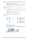
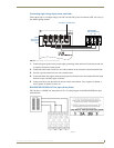
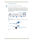
High-Voltage Connections
FIG. 15 shows an example of a high-voltage connection for an RE-DM4 controller. Each AMX Lighting
module has its high-voltage connectors marked on its circuit board. Line, load, and neutrals are also
clearly marked.
The clearance above and below the enclosure is necessary for proper ventilation and
heat dissipation.
Refer to the Dimmer Enclosures with Breakers installation guide for more
information.
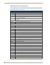
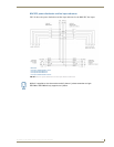
FIG. 14 Center-line reference points and dimensions
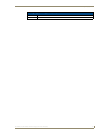
FIG. 15 High-voltage connections for an RE-DM4
A to B
B to C
Bottom slot
Top slot
Configuration for
right and left
mounting brackets
for all Radia
enclosures.
Maximum mounting
screw size: #12
Distance: B to C:
RDA-ENC2 - 11.0" (279.4 mm)
RDA-ENC4 - 11.0" (279.4 mm)
RDA-ENC6 - 11.0" (279.4 mm)
RDA-ENC6B - 22.88" (581.2 mm)
RDA-ENC12B - 22.88" (581.2 mm)
Distance: A to B:
RDA-ENC2 - 5.25" (133.3 mm)
RDA-ENC4 - 10.0" (254.0 mm)
RDA-ENC6 - 16.0" (406.4 mm)
RDA-ENC6B - 16.0" (406.4 mm)
RDA-ENC12B - 16.0" (406.4 mm)
Neutral
Line in
Load
Load