


ADSP-TS201S
Rev. C | Page 15 of 48 | December 2006
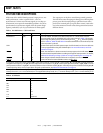
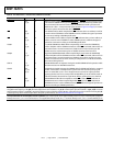
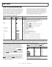
Table 7. Pin Definitions—External Port DMA/Flyby
Signal Type Term Description
DMAR3–0
I/A epu DMA Request Pins. Enable external I/O devices to request DMA services from the DSP.
In response to DMARx, the DSP performs DMA transfers according to the DMA
channel’s initialization. The DSP ignores DMA requests from uninitialized channels.
IOWR
O/T
(pu_0)
nc I/O Write. When a DSP DMA channel initiates a flyby mode read transaction, the DSP
asserts the IOWR
signal during the data cycles. This assertion makes the I/O device
sample the data instead of the TigerSHARC.
IORD
O/T
(pu_0)
nc I/O Read. When a DSP DMA channel initiates a flyby mode write transaction, the DSP
asserts the IORD signal during the data cycle. This assertion with the IOEN makes the
I/O device drive the data instead of the TigerSHARC.
IOEN
O/T
(pu_0)
nc I/O Device Output Enable. Enables the output buffers of an external I/O device for fly-
by transactions between the device and external memory. Active on flyby
transactions.
I = input; A = asynchronous; O = output; OD = open-drain output; T = three-state; P = power supply; G = ground; pd = internal pull-down
5kΩ; pu = internal pull-up 5 kΩ; pd_0 = internal pull-down 5 kΩ on DSP ID = 0; pu_0 = internal pull-up 5 kΩ on DSP ID = 0; pu_od_0 = internal
pull-up 500
Ω on DSP ID = 0; pd_m = internal pull-down 5 kΩ on DSP bus master; pu_m = internal pull-up 5 kΩ on DSP bus master; pu_ad
= internal pull-up 40 kΩ. For more pull-down and pull-up information, see Electrical Characteristics on Page 22.
Term (termination of unused pins) column symbols: epd = external pull-down approximately 5 k
Ω to V
SS
; epu = external pull-up approx-
imately 5 k
Ω to V
DD_IO
, nc = not connected; na = not applicable (always used); V
DD_IO
= connect directly to V
DD_IO
; V
SS
= connect directly to V
SS