


ADSP-TS201S
Rev. C | Page 31 of 48 | December 2006
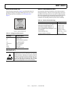
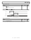
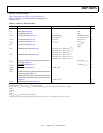
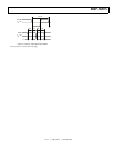
Link Port—Data Out Timing
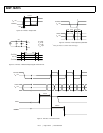
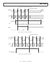
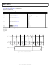
Table 32 with Figure 18, Figure 19, Figure 20, Figure 21,
Figure 22, and Figure 23 provide the data out timing for the
LVDS link ports.
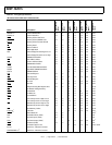
Table 32. Link Port—Data Out Timing
Parameter Description Min Max Unit
Outputs
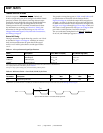
t
REO
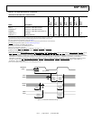
Rising Edge (Figure 19)350ps
t
FEO
Falling Edge (Figure 19)350ps
t
LCLKOP
LxCLKOUT Period (Figure 18) Greater of 2.0 or
0.9 × LCR × t
CCLK
1, 2, 3
Smaller of 12.5 or
1.1 × LCR × t
CCLK
1, 2,
3
ns
t
LCLKOH
LxCLKOUT High (Figure 18)0.4× t
LCLKOP
1
0.6 × t
LCLKOP
1
ns
t
LCLKOL
LxCLKOUT Low (Figure 18)0.4× t
LCLKOP
1
0.6 × t
LCLKOP
1
ns
t
COJT
LxCLKOUT Jitter (Figure 18) ±150
4,
5,
6
±250
7
ps
ps
t
LDOS
LxDATO Output Setup (Figure 20)0.25 × LCR × t
CCLK
–0.10 × t
CCLK
1, 4, 8
0.25 × LCR × t
CCLK
–0.15 × t
CCLK
1,
5,
6,
8
0.25 × LCR × t
CCLK
–0.30 × t
CCLK
1,
7,
8
ns
ns
ns
t
LDOH
LxDATO Output Hold (Figure 20)0.25 × LCR × t
CCLK
–0.10 × t
CCLK
1, 4, 8
0.25 × LCR × t
CCLK
–0.15 × t
CCLK
1,
5,
6,
8
0.25 × LCR × t
CCLK
–0.30 × t
CCLK
1,
7,
8
ns
ns
ns
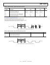
t
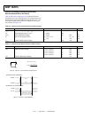
LACKID
Delay from LxACKI rising edge to first transmission
clock edge (Figure 21)
16 × LCR × t
CCLK
1, 2
ns
t
BCMPOV
LxBCMPO Valid (Figure 21)2× LCR × t
CCLK
1, 2
ns
t
BCMPOH
LxBCMPO Hold (Figure 22)3× TSW – 0.5
1, 9
ns
Inputs
t
LACKIS
LxACKI low setup to guarantee that the transmitter
stops transmitting (Figure 22)
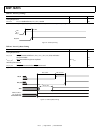
LxACKI high setup to guarantee that the transmitter
continues its transmission without any interruption
(Figure 23)16× LCR × t
CCLK
1, 2
ns
t
LACKIH
LxACKI High Hold Time (Figure 23)0.51 ns
1
Timing is relative to the 0 differential voltage (V
OD
= 0).
2
LCR (link port clock ratio) = 1, 1.5, 2, or 4. t
CCLK
is the core period.
3
For the cases of t
LCLKOP
= 2.0 ns and t
LCLKOP
= 12.5 ns, the effect of t
COJT
specification on output period must be considered.
4
LCR= 1.
5
LCR= 1.5.
6
LCR= 2.
7
LCR= 4.
8
The t
LDOS
and t
LDOH
values include LCLKOUT jitter.
9
TSW is a short-word transmission period. For a 4-bit link, it is 2 × LCR × t
CCLK
. For a 1-bit link, it is 8 × LCR × t
CCLK
ns.