


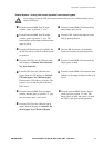

Operation – Operation Procedures
990-2282A-001 Smart-UPS® VT 10-40 kVA 400V, 208V, 200V – Operation 11
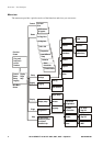
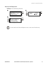
Parallel System – turning into normal operation from external bypass.
Caution
Never attempt to turn the UPS into normal operation till you have verified that there are no
internal UPS faults.
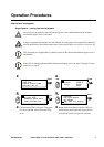
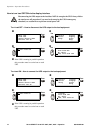
From the external MBP: Turn all input
switches (
Q001) to position “1” (ON).
From the external MBP: Check that all the
output lamps
(Q002) are lit.
From the external MBP: Turn all output
switches
(Q002) to position “1” (ON). The
lamp indicator of the output isolation breaker
(Q004) is still lit.
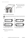
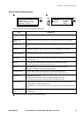
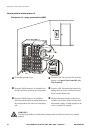
From the UPS: Connect the batteries in the
UPS by pushing them in.
From the XR Enclosure(s) (if available): Set
the DC disconnect switch (if available) to the
ON position.
From the XR Enclosure(s) (if available):
Connect the batteries by pushing them in.
From the UPS: Turn ON all UPS units from
each display via Control–Turn Load ON–
Yes, Turn Load ON.
From the external MBP: Check that all the
lamps (
Q002) are unlit.
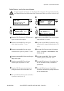
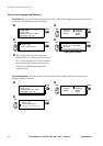
From the UPS: Turn the UPS units into
bypass from one UPS display via Control–
UPS into bypass–Yes, UPS into bypass.
Check that the UPS units are in bypass. The
green (
LOAD ON) and the yellow (BYPASS)
LEDs are lit.
From the external MBP: Check that the lamp
indicator of the output isolation breaker is lit
(
Q004).
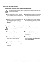
From the external MBP: Turn the output
isolation breaker (
Q004) to position “1” (ON).
Now the lamps
(Q003 + Q004) are lit.
From the external MBP: Turn the bypass
switch (
Q003) to position “0” (OFF). The
lamps (
Q004) are unlit, but (Q003) is lit until
the UPS is running in normal operation.
From the UPS: Turn the UPS units out of
bypass from the display via Control–UPS
out of bypass–Yes, UPS out of bypass.