


ASUS Crosshair 2-5
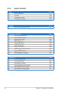
Internal connectors Page
1. Floppy disk drive connector (34-1 pin FLOPPY) 2-28
2. IDE connector (40-1 pin PRI_IDE) 2-28
3. NVIDIA
®
NF590-SLI Southbridge Serial ATA connectors
(7-pin SATA1 [blue], SATA2 [blue], SATA3 [blue], SATA4 [blue],
SATA5 [blue], SATA6 [blue])
2-29
4. USB connectors (10-1 pin USB56, USB78) 2-30
5. IEEE 1394a port connector (10-1 pin IE1394_2) 2-30
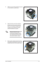
6. CPU, chassis, and optional fan connectors (4-pin CPU_FAN,
3-pin CHA_REAR_FAN, 3-pin CHA_FRONT_FAN, 3-pin
OPT_FAN1, 3-pin OPT_FAN2, 3-pin OPT_FAN3, 3-pin
OPT_FAN4, 3-pin OPT_FAN5)
2-31
7. Chassis intrusion connector (4-1 pin CHASSIS) 2-31
8. ATX power connectors (24-pin EATXPWR, 8-pin EATX12V, 2-32
9. System panel connector (20-pin PANEL)
•
System power LED (Green 3-pin PLED)
•
Hard disk drive activity LED (Red 2-pin IDE_LED)
•
System warning speaker (Orange 4-pin SPEAKER)
•
ATX power button/soft-off button (Yellow 2-pin PWR)
•
Reset button (Blue 2-pin RESET)
2-33
10. Thermo sensor cable connectors (WJ1/2/3, 2-pin) 2-34
Onboard switches Page
1. Clear CMOS switch 2-33
2. Power-on switch 2-33
3. Reset switch 2-34