


18 ASUS XG-DLS User’s Manual
CPU
III. INSTALLATION
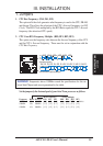
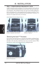
3. Central Processing Unit (CPU)
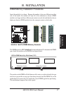
This motherboard provides two Single Edge Contact (SEC) Slot 2 connectors for
either one or two Intel
®
Xeon™ processors packaged in an SEC cartridge. When
only one processor is used, the other Slot 2 connector must be terminated with the
provided front side bus termination module.
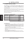
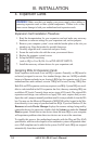
NOTE: The pictures in the following pages will have the same item numbers
next to them for your reference. The following pictures are for reference only
and are not to size. The design and color of your items may be slightly different.
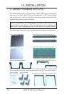
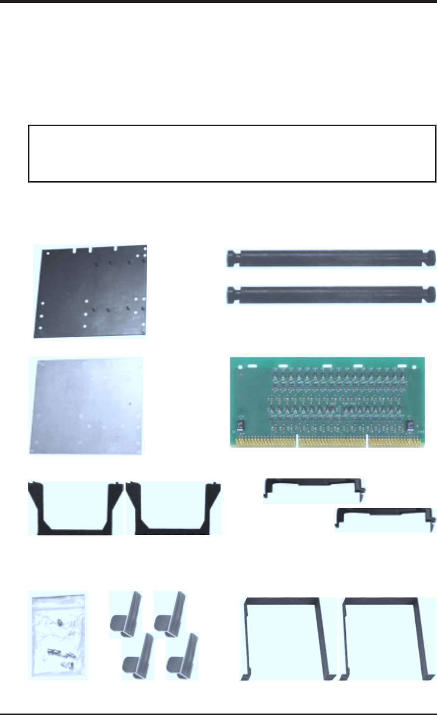
You should check to see that you have the following items with your motherboard:
III. INSTALLATION
(Item 1) Metal Baseboard x 1
(Item 2) Rubber Pad x 1
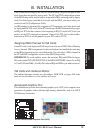
NOTE: For the retention mechanism and lock bar, there is a left and a right side. The left side has a single
dot and the right side has two dots (when holding the motherboard with the ATX connectors to the left).
(Item 4) Captive
Nut x 15 (in bag)
(Item 5) Cartridge
Lifter x 4 (Item 9) Retention Mechanism Support Frame x 2
(Item 3) Retention Mechanism x 2
(Item 8) Retention Mechanism Cap x 2
(Item 6) Retention Mechanism Brace Bar x 2
(Item 7) Front Side Bus Termination Module