


ASUS XG-DLS User’s Manual 33
III. INSTALLATION
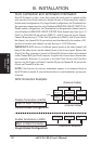
Connectors
III. INSTALLATION
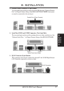
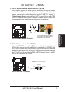
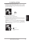
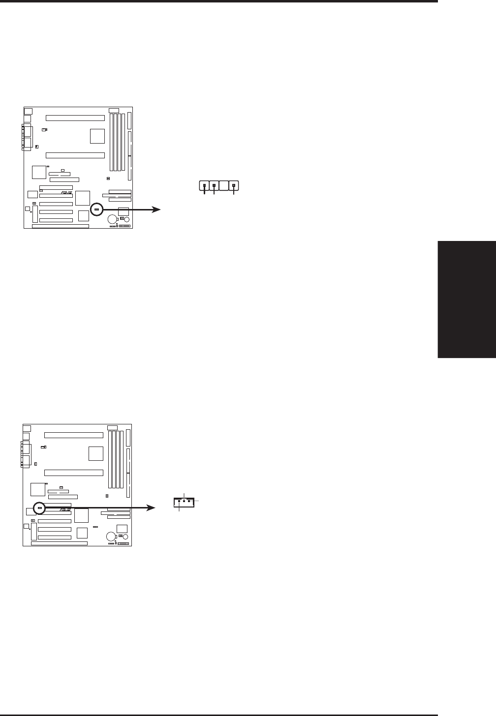
20. Chassis Intrusion Sensor Lead (4-1 pin CHASSIS)
This lead is for a chassis intrusion monitor or sensor. The sensor is triggered
when a high level signal is sent to the “chassis signal” lead. This occurs when a
panel switch or light detector is triggered. This function requires optional trig-
ger switches to be installed.
R
XG-DLS
XG-DLS Chassis Open Alarm Lead
CHASSIS
+5VSB
Chassis
Ground
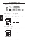
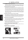
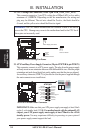
21. Wake-On-LAN Connector (3-pin WOLCON)
These connector connects to LAN cards with a Wake On LAN output, such as
the ASUS PCI-L101. The connector powers up the system when a wakeup packet
or signal is received through the LAN card.
IMPORTANT: This feature requires that the WAKE On LAN Power Up Con-
trol is set to Enabled (see “Power Management Setup” under BIOS SOFT-
WARE section) and that your system has an ATX power supply with at least
720mA +5V standby power.
R
XG-DLS
IMPORTANT: Requires an ATX power
supply with at least 720mA +5Volt
standby power
+5 Volt Standby
PME
Ground