


20 ASUS XG-DLS User’s Manual
III. INSTALLATION
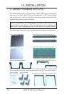
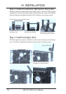
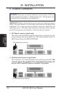
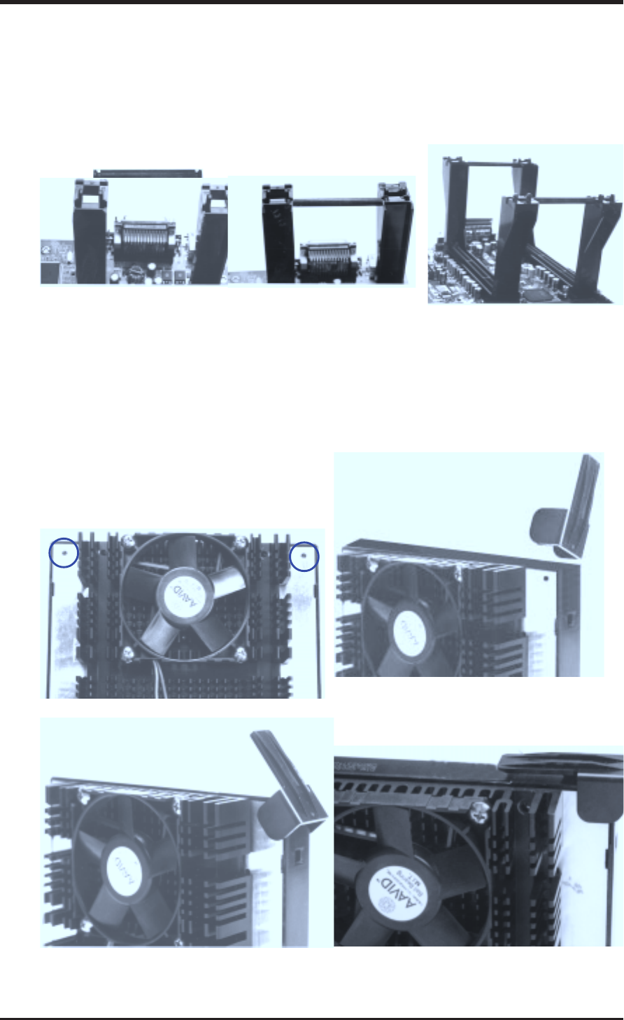
Step 3: Install the Retention Mechanism Brace Bars
Place the retention mechanism brace bar into the groove on the top of the retention
mechanism as shown in the picture below. These pictures are views of the mother-
board and retention mechanism with the ATX connectors away from yourself.
(Item 6) Retention Mechanism Brace Bar
Retention mechanism with
brace bar on top
One retention mechanism
with brace bar installed
Both retention mechanisms
with both brace bars installed
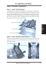
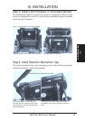
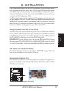
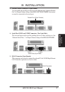
Step 4: Install Cartridge Lifters
Each Xeon processor requires two lifters in order to allow safe removal of the pro-
cessor. The lifters clamps the cartridge on the two holes at each top corner.
Installed lifter in a colapsed positionHalf-colapsed lifter after installation
One lifter being inserted over the
cartridge from a vertical position
(Item 5) CPU Lifter
Location of lifter installation holes
CPU
III. INSTALLATION