


ASUS XG-DLS User’s Manual 29
III. INSTALLATION
Connectors
III. INSTALLATION
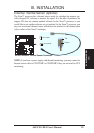
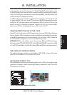
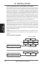
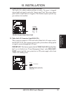
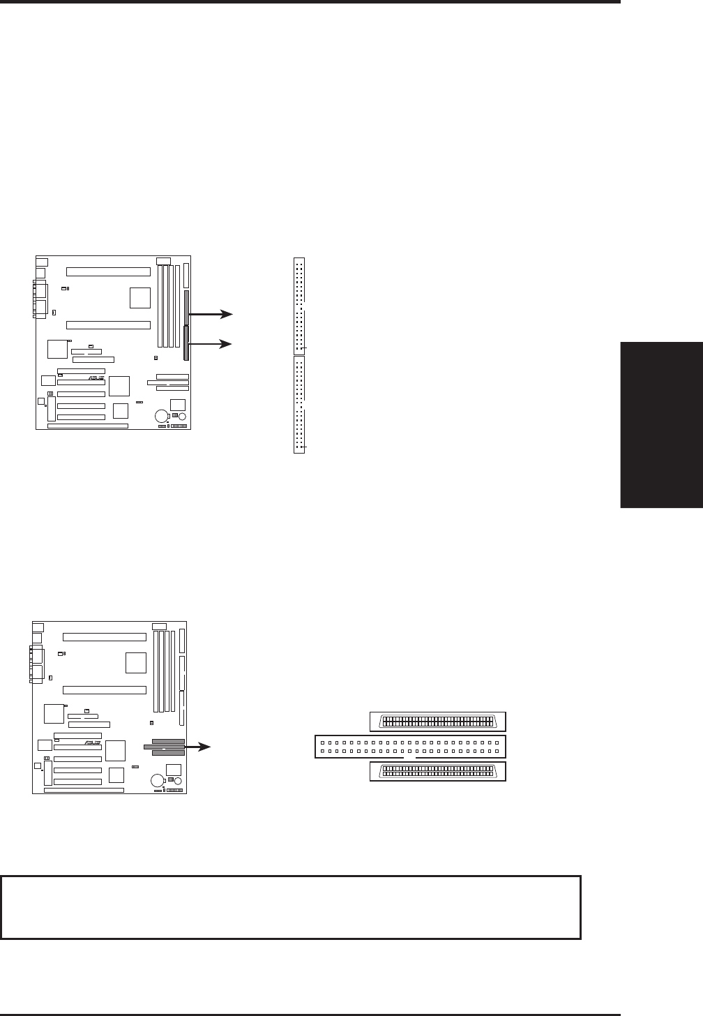
9. Primary / Secondary IDE connectors (Two 40-1pin IDE)
These connectors support the provided IDE hard disk ribbon cable. After con-
necting the single end to the board, connect the two plugs at the other end to
your hard disk(s). If you install two hard disks, you must configure the second
drive to Slave mode by setting its jumper accordingly. Please refer to the docu-
mentation of your hard disk for the jumper settings. BIOS now supports SCSI
device or IDE CD-ROM bootup (see “HDD Sequence SCSI/IDE First” & “Boot
Sequence” in the BIOS Features Setup of the BIOS SOFTWARE) (Pin 20 is
removed to prevent inserting in the wrong orientation when using ribbon
cables with pin 20 plugged).
R
XG-DLS
XG-DLS IDE Connectors
NOTE: Orient the
red stripe to PIN 1
Primary
Secondary
Primary IDE Connector
PIN 1
PIN 1
Secondary IDE Connector
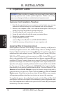
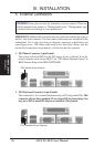
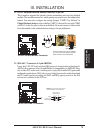
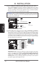
10. Ultra-Fast (50-pin)/Ultra2 (68-pin) SCSI Connectors
This motherboard has an onboard 50-Pin Ultra-Fast SCSI connector for 8-bit
SCSI devices and two 68-Pin Ultra2 SCSI connectors for Low Voltage Devices
(LVD) and 32-bit Ultra-Wide SCSI devices.
R
XG-DLS
XG-DLS Onboard SCSI Connectors
50-pin Ultra-Fast
SCSI Connector
(Channel B)
68-pin Ultra2 SCSI Connector
(Channel A)
68-pin Ultra2 SCSI Connector
(Channel B)
1
68
341
35
68
341
35
IMPORTANT! Please read the SCSI connection and termination information on
the next page.