


22 ASUS XG-DLS User’s Manual
CPU
III. INSTALLATION
III. INSTALLATION
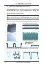
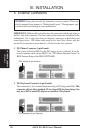
Step 7: Install Retention Mechanism Frame
In order to keep the retention mechanism lock bar from coming free and to add extra
stability to the plastic retention mechanisms, a metal frame is used accross both reten-
tion mechanisms. After installing the frame, four captive nuts should be tightened on
the feet of the frame to the screws protruding from the retention mechanisms. This is
the end of the Xeon™ processor installation and you should have 4 extra (only 11 is
used out of 15) captive nuts in case you loose any.
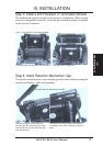
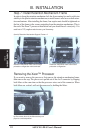
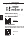
Removing the Xeon™ Processor
If you want to remove the processor, first remove the retention mechanism frame,
then remove the cap. The processor is pulled out of the slot 2 connector by flipping
both lifters at the same time so that the processor raises out of the connector. When
both lifters are vertical, pull out the processor by holding the lifters.
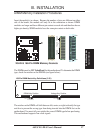
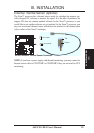
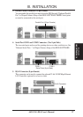
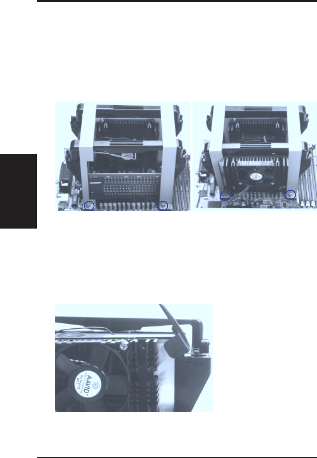
(Item 9) Retention Mechanism Support Frame x 2
Retention mechansim fram around single
processor configuration with terminator.
Retention mechansim fram around dual
processor configuration.
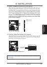
The processor raised out of the slot 2 connector
by the reverse force of the lifters as they are
pryed to a vertical position.