


34 ASUS XG-DLS User’s Manual
Connectors
III. INSTALLATION
III. INSTALLATION
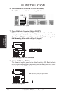
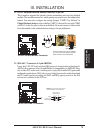
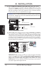
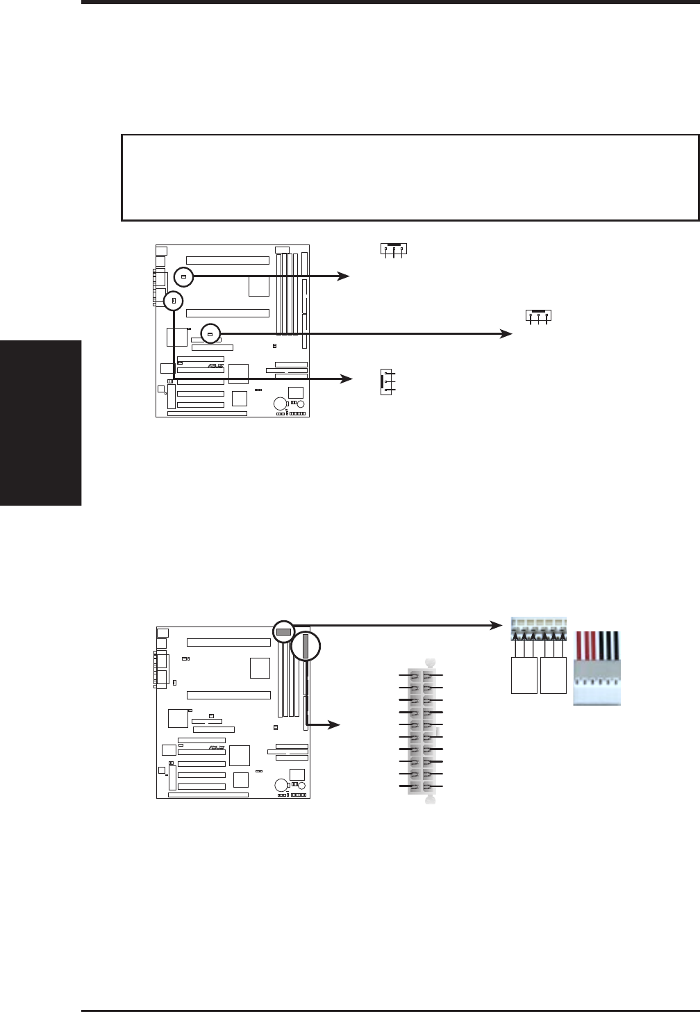
22. CPU Cooling Fan Connectors (Three 3-pin PWR_/CHA_/CPU_FAN)
This connector supports a 3-pin CPU cooling fan of 500mA (6W) or less with a
minimum of 3,500RPM. Depending on the fan manufacturer, the wiring and
plug may be different. The red wire should be Positive, the black should be
Ground, and the yellow wire should be Rotation signal.
WARNING! The CPU and/or motherboard will overheat if there is no airflow
across the CPU. Damage may occur to the motherboard and/or the CPU fan if
these pins are incorrectly used.
R
XG-DLS
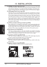
XG-DLS 12Volt Cooling Fan Power
Power Supply Fan Power
Ground
Rotation
+12V
Ground
Rotation
+12V
CPU Fan Power
Ground
Rotation
+12V
Chassis Fan Power
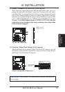
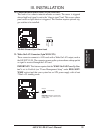
23. ATX/Auxilliary Power Supply Connector (20-pin ATXPWR/ 6-pin PWR3V)
This connector connects to a ATX power supply. The plug from the power supply
will only insert in one orientation because of the different hole sizes. Find the proper
orientation and push down firmly but gently making sure that the pins are aligned.
An auxilliary connector (PWR3V) is provided in case the power supplied through
the main connectors are insufficient.
R
XG-DLS
XG-DLS ATX/AUX Power Connector
+3.3Volts
-12.0Volts
Ground
PWR Supply On
Ground
Ground
Ground
-5.0 Volts
+5.0 Volts
+5.0 Volts
Power Good
+12.0Volts
+3.3 Volts
+3.3 Volts
Ground
+5.0 Volts
Ground
+5.0 Volts
Ground
+5V Standby
PWR3V
ATXPWR
BLK
BLK
BLK
RED
RED
RED
Ground
+3Volts
IMPORTANT: Make sure that your ATX power supply can supply at least 10mA
on the 5-volt standby lead (5VSB). For motherboards with the onboard LAN
chipset, your ATX power supply must supply at least 720mA to the +5Volt
standby power. You may experience difficulty in powering on your system if
your power supply cannot support the load.