


ASUS XG-DLS User’s Manual 31
III. INSTALLATION
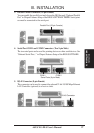
Connectors
III. INSTALLATION
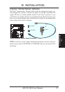
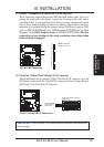
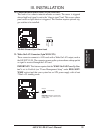
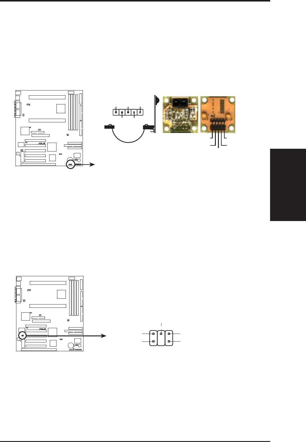
11. IrDA-Compliant infrared module connector (5-pin IR)
This connector supports the optional wireless transmitting and receiving infrared
module. This module mounts to a small opening on system cases that support this
feature. You must also configure the setting through “UART2 Use Infrared” in
Chipset Features Setup to select whether UART2 is directed for use with COM2
or IrDA. Use the five pins as shown on the Back View and connect a ribbon cable
from the module to the motherboard according to the pin definitions.
R
XG-DLS
Front View
XG-DLS Infrared Module Connector
For the infrared feature to be available,
you must connect the optional Infrared
(IrDA) module to the motherboard
+5V
IRRX
IRTX
(NC)
GND
+5V
IRTX
IRRX
(NC)
GND
Back View
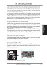
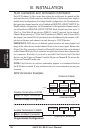
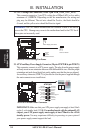
12. SB-Link™ Connector (6-1 pin SBLINK)
Using Intel’s PC-PCI and serialized IRQ protocols found in this motherboard’s
AGPset, this connector allows Sound Blaster 16 compatibility to AWE64D (Digi-
tal) or other PCI audio cards, enabling users to play Real-mode DOS games and
multimedia applications. SB-Link acts as a bridge between the motherboard and
the PCI audio card by providing the DMA and IRQ signals present in the ISA
bus but not available on the PCI bus.
R
XG-DLS
XG-DLS SB-LINK™ Connector
NOTE: Pin 3 is removed to ensure the
correct orientation of the cable on it.
PC/PCI Grant
Sideband Signal
5
6
PC/PCI Request
Sideband Signal
1
DGND
2
DGND
Serial IRQ
4