


28 ASUS XG-DLS User’s Manual
Connectors
III. INSTALLATION
III. INSTALLATION
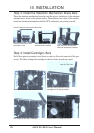
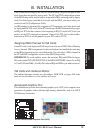
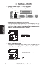
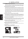
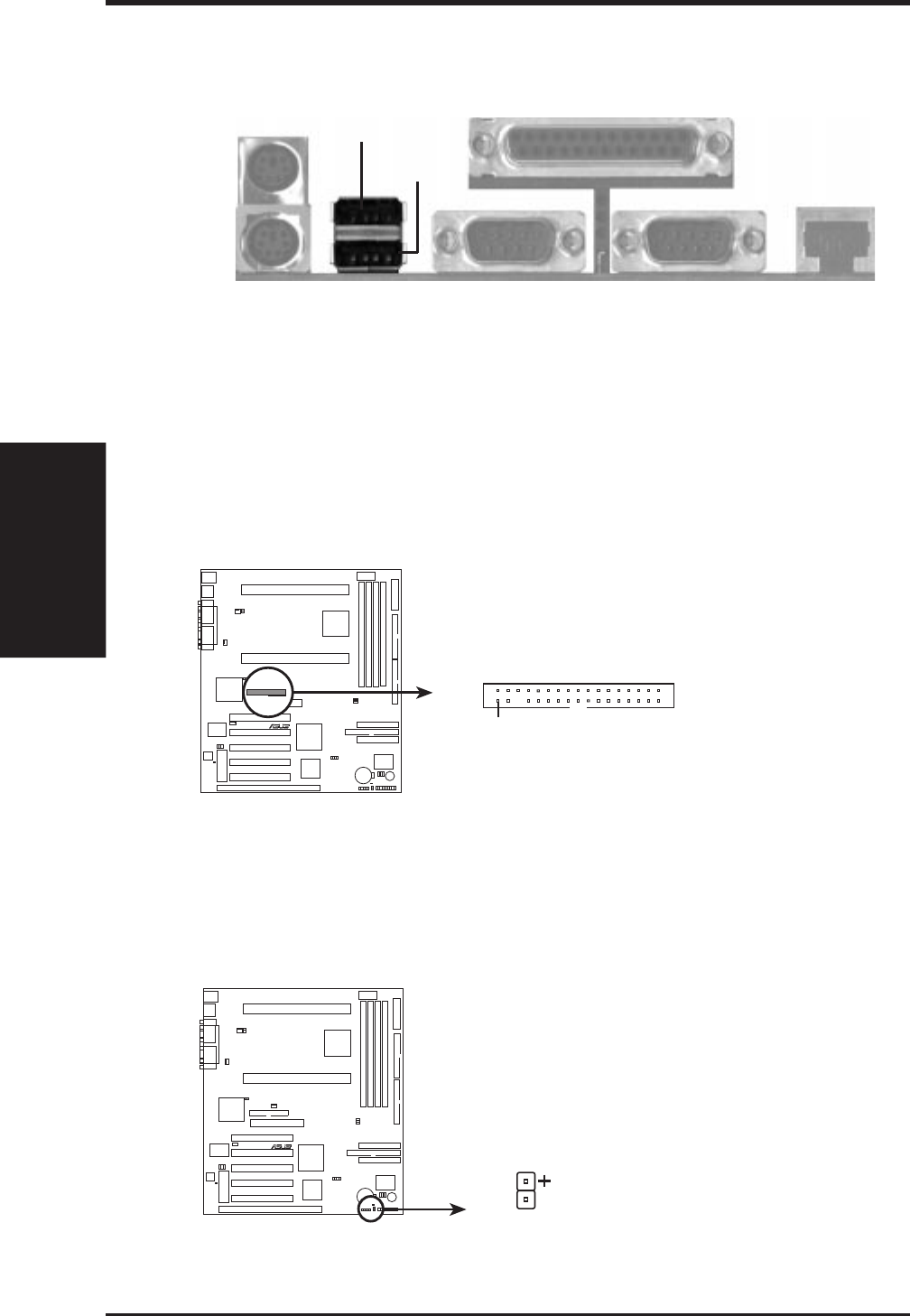
6. Universal Serial BUS Ports 1 & 2 (Two 4-pin Female)
Two USB ports are available for connecting USB devices.
Universal Serial Bus (USB)
USB 2
USB 1
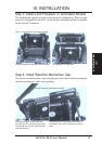
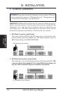
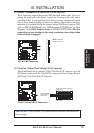
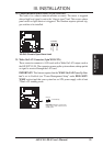
7. Floppy Disk Drive Connector (34-1pin FLOPPY)
This connector supports the provided floppy disk drive ribbon cable. After con-
necting the single end to the board, connect the two plugs on the other end to the
floppy drives. (Pin 5 is removed to prevent inserting in the wrong orienta-
tion when using ribbon cables with pin 5 plugged.)
R
XG-DLS
XG-DLS Floppy Disk Drive Connector
NOTE: Orient the red stripe to Pin 1
Floppy Drive Connector
Pin 1
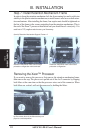
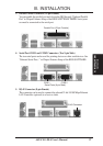
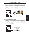
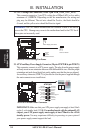
8. Activity LED (2-pins HDLED)
This connector supplies power to the cabinet’s activity LED. Read and write
activity by devices connected to the Primary IDE, Secondary IDE, or SCSI con-
nectors will cause the LED to blink.
TIP: If the case-mounted LED does not light,
try reversing the 2-pin plug.
R
XG-DLS
XG-DLS Activity LED