3. OVERVIEW USER’s CONTROLS
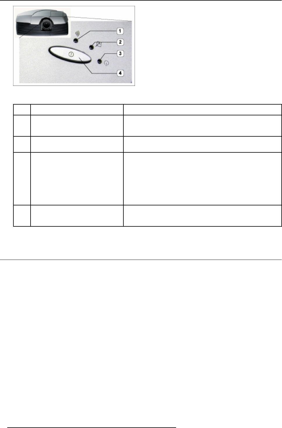
Image 3-2
Cine VERSUM 80 controls
Controls function description
Ref.
Function Description
1 Infra Red Receiver Reception diode for the IR signals from the Remote Control. Allows
switching On/Off (Standby) of the projector separately and controlling
theCineVERSUMMaster.
2 Infra Red Reception LED indicator Lights up when a valid IR signal from the Remote Control has been
captured.
3 Standby LED Lights up continuously: projector in the operation mode.
Lights up repeatedly 2 times short, 1 time long: projector in the standby
mode
Blinks fast: projector in the cooling down mode after switching of
f
(duration 1 min.).
Lights up repeatedly 1 time long, 1 time s hort: projector has been started
up in the cooling down mode, waiting for lamp ignition.
4 Main power switch Button pressed, s witches the projector in the ’Standby’ mode. This mode
is indicated by the standby LE D which lights up repeatedly 2 times short,
1 time long.
Table 3-2
3.3 Cine VERSUM 50
Rear and Front view
The only hardware control on the Cine VERSUM 50 is the Main Power Switch (1), located at the backside of the screen itself. This
switch puts the S creen in the ’OFF’ or Standby position ’ON’. From the Standby position, the operation is controlled by the Cine
VER
SUM M aster.
The s tatus of the Plasm a screen is indicated by a blue LED (3), located at the bottom on the right of the s creen. In the same corner
an IR LED (2) is mounted .
8
R5976490 CINE VERSUM SYSTEM 17012003


