


724-746-5500 | blackbox.com
724-746-5500 | blackbox.com
Page 13
Chapter 3: Hardware Installation
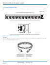
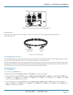
Figure 3-4. USB cable connected to PoE Gigabit Injector.
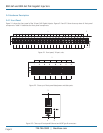
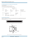
AC power cord
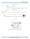
Connect the AC power cable to the AC power connector on the rear of the PoE Gigabit Injector and the power
outlet. See Figure 3-5.
IEC-320 power
connnector
AC power
plug
Figure 3-5. AC power cord.
3.4 Powering On the Unit
The PoE Gigabit Injector receives power via the power cord. To apply or remove power to/from the PoE Gigabit Injector, connect
or disconnect the AC power cable to/from the AC power connector on the rear of the unit.
With AC power applied, the unit starts up and the internal fans are active. The device runs through a quick power-on test, which
takes less than 10 seconds. During this period, all ports are initially disabled and the port indicators light up. The sequence of the
port LEDs are shown in Section 3.5. Ports are now operating under normal conditions.
3.5 LED Indicators
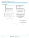
3.5.1 Cold Start
1. AC LED turns greenÆremains on
2. Ethernet LED turns greenÆredÆgreenÆturns offÆredÆturns off (unless connected)
3. 24 ports (with ports connected)ÆLED turns orangeÆgreenÆorangeÆgreenÆturns offÆLED turns green individuallyÆPorts 1,
9, 17ÆPorts 2, 10, 18ÆPorts 3, 11, 19ÆPorts 4, 12, 20ÆPorts 5, 13, 21ÆPorts 6, 14, 22Æ Ports 7, 15, 23ÆPorts 8, 16, 24Æall
24 ports are connectedÆLED remains green
4. 24 ports (without ports connected)ÆLED turns orangeÆgreenÆorangeÆgreenÆturns offÆLED blinks orange individually
Ports 1, 9, 17ÆPorts 2, 10, 18ÆPorts 3, 11, 19ÆPorts 4, 12, 20ÆPorts 5, 13, 21ÆPorts 6, 14, 22ÆPorts 7, 15, 23ÆPorts 8, 16,
24Æblinks orange across all 24 ports