


724-746-5500 | blackbox.com
Page 14
724-746-5500 | blackbox.com
802.3af and 802.3at PoE Gigabit Injectors
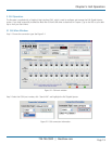
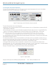
3.5.2 Click System Reset on the Graphical User Interface (GUI)
1. AC LED remains green
2. Ethernet LED remains off until the unit is connected
3. 24 ports (with ports connected): same sequence as Cold Start
4. 24 ports (without ports connected): same sequence as Cold Start
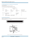
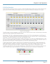
Table 3-1 LED Indicators.
Indicator Conditions
LED Off Green Orange Blinking Orange
Port LED Indicates port is Indicates port is Indicates port has Indicates port is
disabled connected an error disconnected but enabled
Ethernet LED Indicates Ethernet is N/A Indicates NIC is N/A
disconnected from connected to
network network
AC LED Indicates PoE Gigabit Indicates PoE Gigabit N/A N/A
Injector is not powered Injector is powered
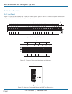
3.6 Rackmounting Installation
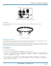
Position the PoE Gigabit Injector on the rack. Line up the mounting bracket with the corresponding screw holes on the PoE
Gigabit Injector. (See Figure 3-6.) Keep the screw area visible to insert screws, and then tighten the screws. (See Figure 3-7.)
Screws and brackets are included in the package.
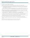
Figure 3-6. 24-port PoE Gigabit Injector with rackmount brackets attached.
Bracket
Screws
PoE Gigabit
Injector
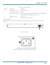
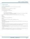
Figure 3-7. Close-up view of rackmounting bracket and screws (side/rear).