


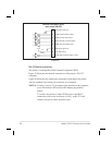
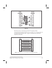

RS-232 Interconnections
The printer is configured as Data Terminal Equipment (DTE).
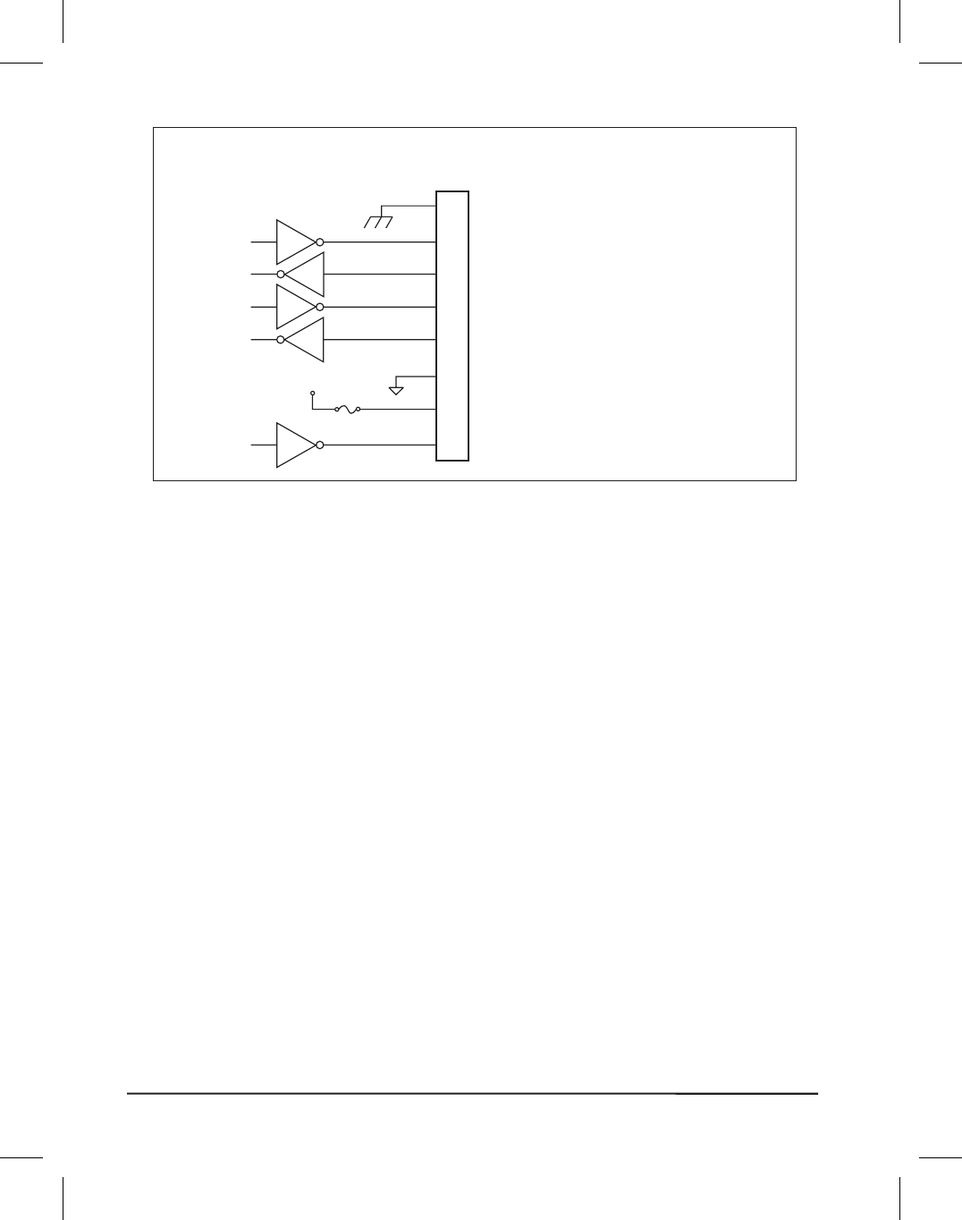
Figure 39 illustrates the internal connections of the printer’s RS-232
connector.
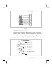
Figure 40 illustrates the connections required to interconnect the printer
with the standard 9-pin serial port connector on a computer.
NOTES: If using a 9-pin to 25-pin adapter plug attached to the computer,
use a null modem cable between the adapter plug and the
printer.
To connect the printer to other DTE devices with DB-25
connectors (such as the serial port of a PC), an RS-232 null
modem (crossover) cable should be used.
94 Brady X-PLUS Series User’s Guide
FG (frame ground)
TXD (transmit data) output
RXD (receive data) input
RTS (request to send) output
DSR (data set ready) input
SG (signal ground)
+5 VDC source
DTR (data terminal ready) output
1
2
3
4
6
7
9
20
1 Amp
F1
+5 V
RS-232 connector (DTE)
rear panel DB-25S
Figure 39