


32
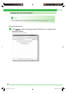
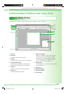
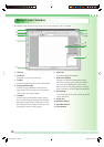
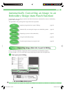
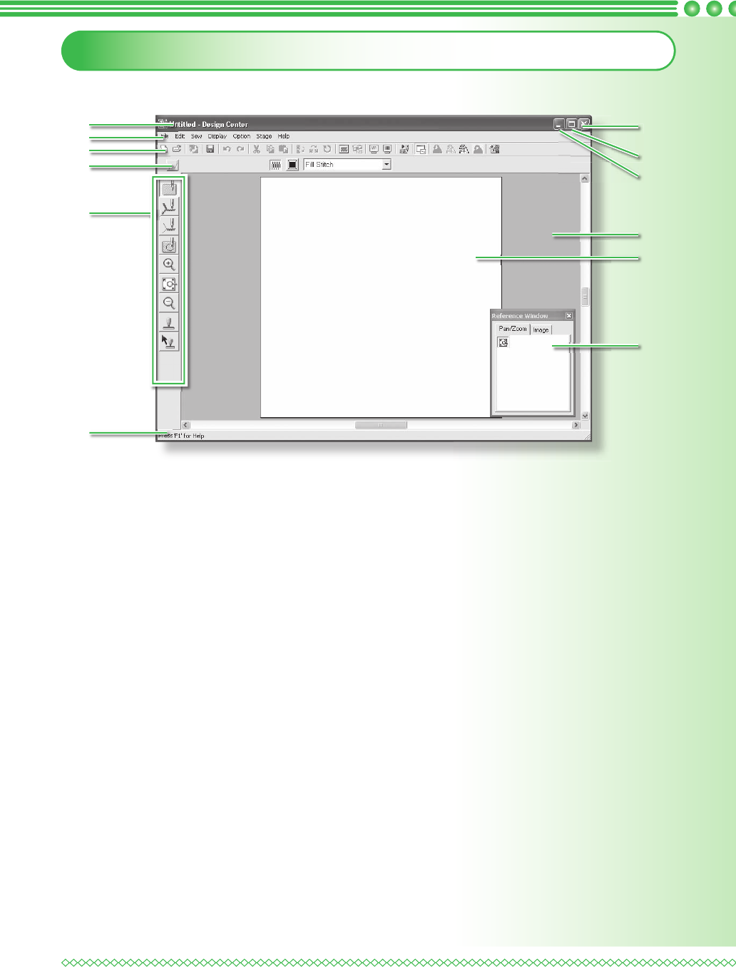
Design Center Window
The default value for the Design Page size in this example is 100 x 100 mm.
1 Title bar
2 Menu bar
Provides access to the functions.
3 Toolbar
Provides shortcuts for the menu commands.
4 Sewing Attributes bar
Sets the sewing attributes (color and sew
type) of the lines and regions in the pattern
(only in the Sew Setting Stage)
5 Tool Box
Used to select and edit the image or pat-
tern. Original Image Stage has no Tool Box;
the other stages all have a different tools in
the Tool Box (The window for the Sew Set-
ting Stage is shown on this page.).
6 Status bar
Provides helpful information.
7 Reference Window
Displays all outlines and patterns in the
work area, giving you an overview while
you work on a detailed area. (For more
details, refer to “Viewing patterns in the ref-
erence window” of the Instruction Manual.)
8 Design Page
The actual part of the work area that can be
saved and sewn.
9 Work area
10 Minimize button
11 Maximize button
12 Close button
1
2
3
4
5
9
10
11
12
7
8
6
PED7_QSG.indb Sec2:32PED7_QSG.indb Sec2:32 02.06.2006 20:07:1202.06.2006 20:07:12