


23 Product Overview
WLA-AWCG User Manual
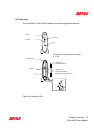
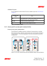
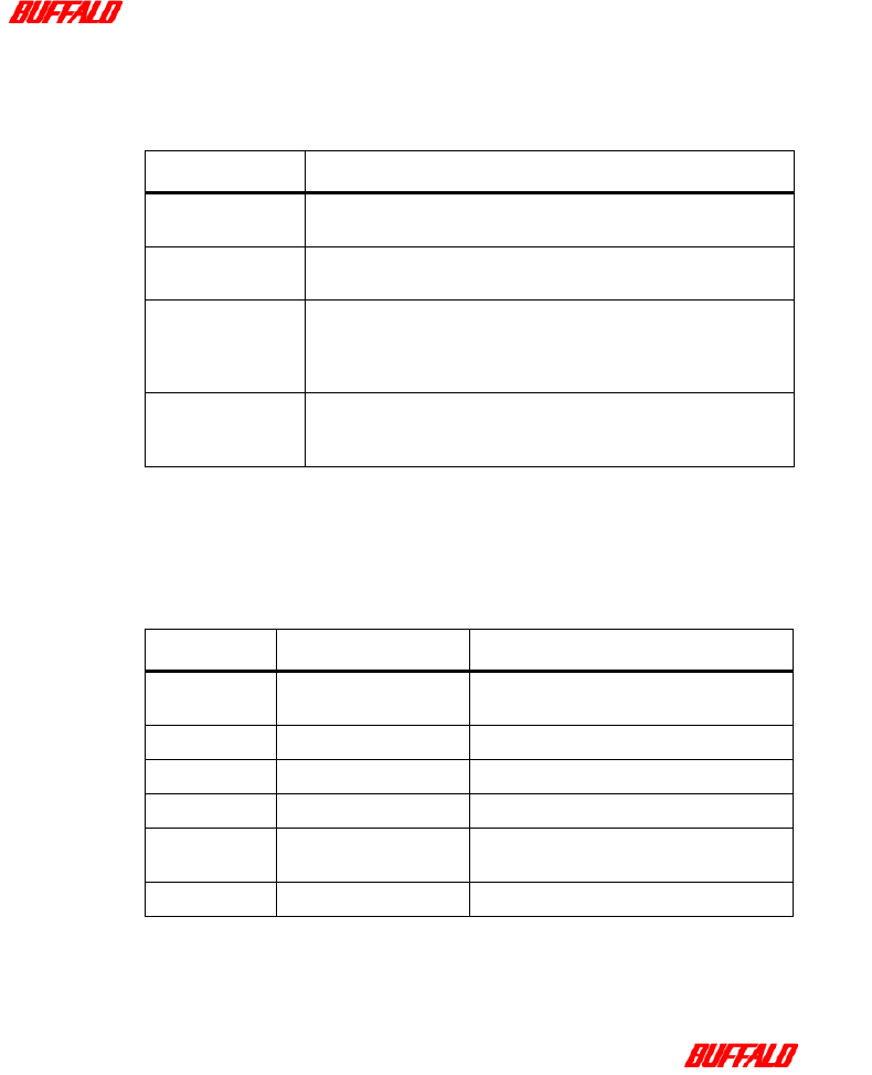
As shown in the diagram above, the AirStation Pro has four LED indicators, each
indicator relaying important information to the user. This information is described
in the following table:
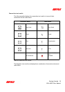
Diagnostic Indicator
Each flash of the Diagnostic indicator conveys a particular error message. These
are as follows:
LED Indicator Message
POWER When the AirStation Pro is connected to a power supply, the LED
indicator will display green continuously.
WIRELESS When the AirStation Pro is successfully connected to a Wireless
LAN, the LED indicator will flash green.
ETHERNET (Wired
LAN)
When the AirStation Pro is connected to a 100Base-TX/10Base-T,
the LED indicator will flash.
10Mbps: Indicator will flash orange.
100Mbps: Indicator will flash green.
DIAGNOSTICS This light will flash when an error has occurred. The flashing fre-
quency indicates the error type, see “Diagnostic Indicator” on
page 23
Table 6: LED indicator function
No. of flashes Status Explanation
1 RAM check error Cannot read or write to the internal mem-
ory.
2 ROM check error Cannot read or write to the flash ROM.
3 Ethernet LAN error The Ethernet LAN controller is broken.
4 Wireless LAN error The Wireless LAN controller is broken.
5 Clock error The Clock is not set correctly or the clock
battery may be depleted.
9 Error other than above
Table 7: Diagnostic indicator information