


Appendix C: Optional Installations and Mode Switch Bank Settings
C-6 6H128-08 and 6H129-08 User’s Guide
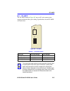
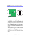
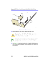
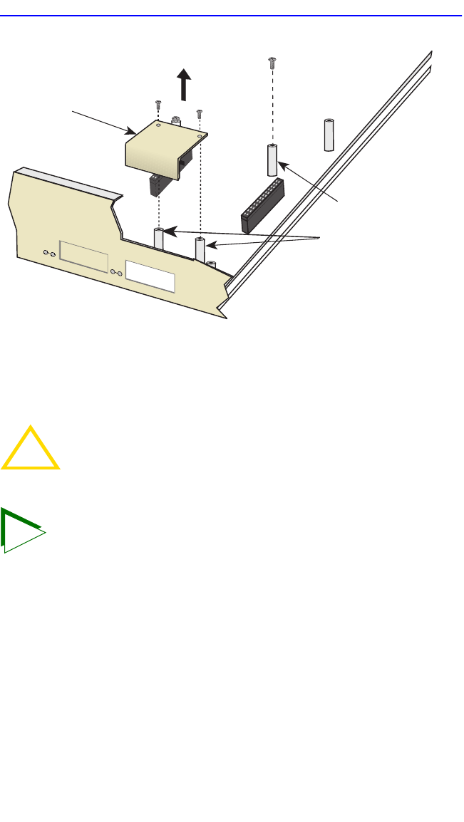
Figure C-3 Coverplate Removal
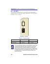
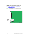
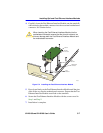
2. Remove the screw from the rear standoff. Save the screw.
3. See Figure C-4. Gently pull the faceplate of the 6H12X-08 forward to
allow room for the Fast Ethernet Interface Modules to be aligned over
the connector.
!
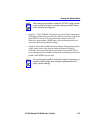
CAUTION
When installing an FE-100FX or FE-100F3 module into the
6H12X-08, remove the rubber plug on the Fast Ethernet
Interface Module before proceeding.
TIP
If the port is not connected to the network right away, reinstall
the rubber plug to reduce the chance of contaminating the
connector.
Front
Standoffs
Rear
Standoff
Coverplate
7
8
2159-32