


COPYRIGHT
©
2001 CANON INC. 2000 2000 2000 2000 CANON iR2200/iR2800/iR3300 REV.0 MAR. 2001
CONTENTS
P2
2.2.2 AC Bias..............................4-5P
2.3 Controlling the Current Voltage/
Current to a Specific Level ......4-5P
2.3.1 Controlling the DC Bias to a
Specific Level ....................4-5P
2.3.2 Controlling the AC Bias to a
Specific Current Level .......4-5P
2.4 Temperature Correction of the DC
Bias ..........................................4-6P
2.5 Humidity Correction of the AC Bias
.................................................4-6P
2.6 Controlling the Detection of the
Photosensitive Drum Resistance
(APVC control)........................4-7P
3 Controlling the Transfer Charging
Roller Bias......................................4-9P
3.1 Outline .....................................4-9P
3.2 Turning On/Off the Bias ........4-10P
3.3 Controlling the Detection of the
Transfer Charging Roller Resistance
(ATVC control) ......................4-10P
3.4 Controlling the Output by Operat-
ing Mode ................................4-11P
3.4.1 Types of Modes ...............4-11P
3.4.2 Turning On/Off the Cleaning
Bias ..................................4-12P
3.5 Controlling the Output ...........4-13P
4 Controlling the Separation Static Elimi-
nator Bias .....................................4-14P
4.1 Outline ...................................4-14P
4.2 Turning On/Off the Bias ........4-15P
4.3 Controlling the Bias to a Specific
Voltage Level .........................4-15P
4.4 Controlling the Output by Paper
Type and Environment Sensor (hu-
midity)....................................4-15P
5 Controlling the Transfer Guide Bias
......................................................4-16P
5.1 Transfer Guide Bias ...............4-16P
6 Primary Charging Roller Cleaning
Mechanism ...................................4-17P
6.1 Outline ...................................4-17P
7 Developing Assembly ..................4-18P
7.1 Outline ...................................4-18P
7.2 Controlling the Developing Bias
...............................................4-19P
7.2.1 Outline .............................4-19P
7.2.2 Controlling the DC Developing
Bias ..................................4-20P
7.2.3 Controlling the AC Developing
Bias ..................................4-20P
7.2.4 Controlling the Level of the DC
Developing Bias ..............4-20P
7.3 Detecting the Level of Toner
...............................................4-21P
8 Drum Cleaner ...............................4-22P
8.1 Outline ...................................4-22P
8.2 Monitoring the Waste Toner Case
...............................................4-24P
8.3 Locking of the Waste Toner
Feedscrew ..............................4-25P
9 Disassembly and Assembly..........4-26P
9.1 Pre-Exposure Lamp Unit .......4-27P
9.1.1 Removing the Pre-Exposure
Lamp Unit........................4-27P
9.2 Photosensitive Drum..............4-28P
9.2.1 Removing the Drum Unit 4-28P
9.2.2 Cleaning the Photosensitive
Drum ................................4-29P
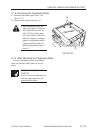
9.3 Transfer Charging Roller .......4-30P
9.3.1 Removing the Transfer Charg-
ing Roller .........................4-30P
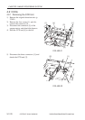
9.4 Charging Roller Solenoid ......4-31P
9.4.1 Removing the Charging Roller
Solenoid (SL6) ................4-31P
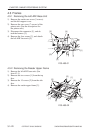
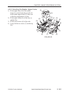
9.5 Developing Assembly ............4-33P
9.5.1 Removing the Developing As-
sembly..............................4-33P
9.5.2 Removing the Grip Assembly
.........................................4-34P
9.5.3 Removing the Toner Sensor
.........................................4-34P
9.5.4 Removing the Developing As-
sembly Upper Cover ........4-34P
9.5.5 Removing the Blade Base Unit
.........................................4-35P
9.5.6 Removing the Developing Cyl-
inder .................................4-35P