


COPYRIGHT
©
2001 CANON INC. 2000 2000 2000 2000 CANON iR2200/iR2800/iR3300 REV.0 MAR. 2001
CHAPTER 4 IMAGE FORMATION SYSTEM
4-9 P
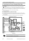
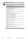
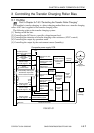
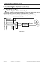
3 Controlling the Transfer Charging Roller Bias
3.1 Outline
Part 2>Chapter 5>7.8.3 “Controlling the Transfer Roller Charging”
The machine’s transfer charging is a direct charging method that uses a transfer charging
roller. A DC bias is applied to the transfer charging roller.
The following relate to the transfer charging system:
[1] Turning on/off the bias.
[2] Controlling the DC bias to a specific voltage/current level.
[3] Controlling the detection of transfer charging roller resistance (ATVC control)
[4] Controlling the output by operation mode
[5] Controlling the output by the environment sensor (humidity)
F04-301-01
DC controller PCB
Transfer
charging
output enable
signal
Cleaning
bias out
Cleaning bias output
ON signal
Transfer output
mode signal 4
Transfer bias output
ON signal
Transfer bias
output control
signal
J301
-B9
J136
-B4
J135
-B8
-B5
J301
-A3
-A1
J136
-A10
-A12
24 VDC input from
main power supply
Composite power supply PCB
PW-CPU
Transformer drive
signal
T133
-B5
-B8
-B6
-B7
-B7
-B6
Transformer drive
signal
Photosensitive
drum
Transfer bias
high-voltage
transformer
(T133)
Transfer cleaning
bias high-voltage
transformer
(T506)
Transfer
bias
output
Transfer
charging roller
Voltage
detection
Voltage level
(ATVC measurement result)
+24V
Environment
sensor
(humidity)
Measurement resultJ302-B14
Serial
communication
Print/standby mode signal
Transfer bias output data
ATVC measurement data
Drive
control
Current
detection
Current
level
Transfer output
mode signal 3
Transfer output
mode signal 2
Transfer output
mode signal 1
Transfer bias output
current switching signal