


COPYRIGHT
©
2001 CANON INC. 2000 2000 2000 2000 CANON iR2200/iR2800/iR3300 REV.0 MAR. 2001
CONTENTS
R2
CHAPTER 3 IMAGE PROCESSING SYSTEM
5.3 Sensors .................................. 2-24R
5.3.1 Removing the Original Detec-
tion Unit.......................... 2-24R
5.3.2 Removing the HP Sensor
........................................ 2-24R
5.3.3 Removing the Original Cover
Sensor ............................. 2-25R
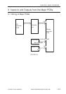
5.4 PCBs ..................................... 2-26R
5.4.1 Removing the Inverter PCB
........................................ 2-26R
1 Outline........................................... 3-1R
2 Analog Image Processing.............. 3-2R
2.1 Outline .................................... 3-2R
2.2 Driving the CCD ..................... 3-2R
2.3 Gain Correction and Offset Correc-
tion of the CCD Output .......... 3-3R
2.4 A/D Conversion of the CCD Output
................................................ 3-3R
3 Digital Image Processing .............. 3-4R
3.1 Outline .................................... 3-5R
3.2 Shading Correction ................. 3-5R
3.2.1 Outline .............................. 3-5R
3.2.2 Shading Adjustment ......... 3-6R
3.2.3 Shading Correction ........... 3-6R
3.2.4 Edge Gain Correction (ADF in
use) ................................... 3-6R
3.3 Auto Density Adjustment (AE)
................................................ 3-7R
3.3.1 Outline .............................. 3-7R
3.3.2 ABC Circuit ...................... 3-7R
3.4 Related Service Mode ............. 3-8R
4 Disassembly and Assembly........... 3-9R
4.1 External Covers..................... 3-10R
4.1.1 External Covers .............. 3-10R
4.1.2 Removing the Reader Right
Cover .............................. 3-10R
4.1.3 Removing the Copyboard Glass
........................................ 3-11R
4.1.4 After Mounting the Copyboard
Glass ............................... 3-11R
4.2 CCDs..................................... 3-12R
4.2.1 Removing the CCD Unit 3-12R
4.2.2 Points to Note When Replacing
the CCD Unit .................. 3-13R
4.3 Frames ................................... 3-14R
4.3.1 Removing the Left ADF Base
Unit ................................. 3-14R
4.3.2 Removing the Reader Upper
Frame .............................. 3-14R
4.3.3 Mounting the Reader Upper
Frame .............................. 3-15R
4.4 PCBs ..................................... 3-16R
4.4.1 Removing the Reader Control-
ler PCB ........................... 3-16R
4.4.2 When Replacing the Reader
Controller PCB ............... 3-16R