


COPYRIGHT
©
2001 CANON INC. 2000 2000 2000 2000 CANON iR2200/iR2800/iR3300 REV.0 MAR. 2001
CONTENTS
P5
CHAPTER 7 EXTERNALS AND CONTROLS
1 Control Panel..................................7-1P
1.1 Outline .....................................7-1P
2 Fans ................................................7-2P
2.1 Arrangement, Functions, and Error
Codes .......................................7-2P
2.2 Operation .................................7-4P
2.2.1 2-Speed Control.................7-4P
2.2.2 Sequence of Operations .....7-4P
3 Power Supply .................................7-5P
3.1 Power Supply ...........................7-5P
3.1.1 Outline ...............................7-5P
3.1.2 Power Outputs ...................7-7P
3.2 Rated Outputs of the Main Power
Supply PCB .............................7-8P
3.3 Rated Output of the Composite
Power Supply PCB ..................7-8P
3.4 Rated Outputs of the Accessories
Power Supply PCB ..................7-9P
3.5 Protective Functions...............7-10P
4 Others ...........................................7-11P
4.1 Silent Mode ............................7-11P
5 Disassembly and Assembly..........7-12P
5.1 External Covers......................7-13P
5.1.1 Removing the Front Cover
.........................................7-14P
5.1.2 Removing the Inside Cover
.........................................7-14P
5.1.3 Removing the Support Cover
.........................................7-15P
5.2 Control Panel .........................7-16P
5.2.1 Removing the Control Panel
.........................................7-16P
5.3 PCBs ......................................7-17P
5.3.1 Removing the DC Controller
PCB..................................7-17P
5.3.2 Points to Note When Replacing
the DC Controller PCB....7-17P
5.3.3 Removing the Controller Cover
.........................................7-17P
5.3.4 Removing the HDD .........7-18P
5.3.5 Removing the HDD Unit
.........................................7-19P
5.3.6 Removing the Controller Box
Unit ..................................7-19P
5.3.7 Removing the Reader Control-
ler PCB ............................7-20P
5.3.8 When Replacing the Reader
Controller PCB ................7-20P
5.3.9 Removing the Main Controller
PCB..................................7-20P
5.3.10 When Replacing the Main Con-
troller PCB .......................7-21P
5.3.11 Removing the Composite Power
Supply..............................7-21P
5.3.12 Removing the Accessories
Power Supply...................7-21P
5.3.13 Removing the Main Power Sup-
ply ....................................7-22P
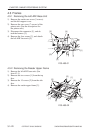
4.1.4 Removing the Fixing Stepped
Gear .................................6-13P
4.1.5 Removing the Fixing Film Unit
.........................................6-13P
4.1.6 Removing the Roller Bushing,
Conducting Rubber, and Fixing
Roller ...............................6-14P
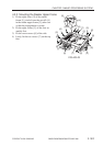
4.1.7 Removing the Cleaning Roller
Unit ..................................6-16P
4.1.8 Removing the Lower Guide
Ribs ..................................6-16P
4.1.9 Removing the Fixing Drive Unit
.........................................6-17P
4.1.10 Mounting the Locking Cam
Unit ..................................6-17P