COPYRIGHT
©
2001 CANON INC. 2000 2000 2000 2000 CANON iR2200/iR2800/iR3300 REV.0 MAR. 2001
CHAPTER 1 GENERAL DESCRIPTION
1-14 S
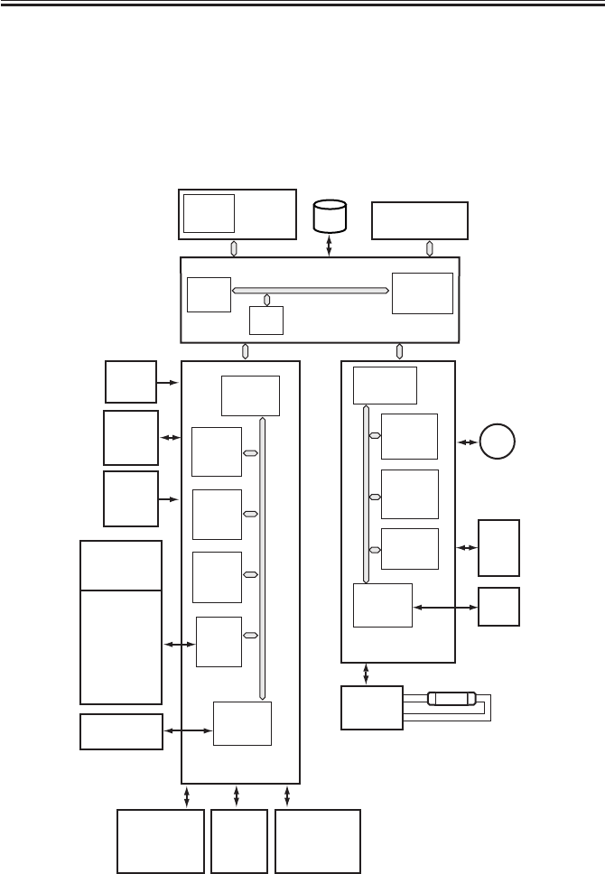
3.2 Outline of the Electrical Circuitry
3.2.1 Construction of the Electrical Circuit
The major electrical mechanisms of the machine are controlled by the following PCBs:
[1] Man controller PCB; controls the system as a whole, processes images
[2] DC controller PCB; controls the printer unit, controls the finisher communication
[3] Reader controller PCB; controls the reader unit, controls the DADF communication
F01-302-01
ADF
LAMP1
M400
CPU
(IC300)
CPU
(IC1010)
SRAM
(IC302)
RAM
IPC
(IC309)
ROM
(IC301)
PIO
(IC303)
ROM
(IC401)
HDD
CPU
(IC6501)
DIMM
ROM
CPU
(IC400)
RAM
(IC402)
EEPROM
(IC403)
GATE
ARRAY
(IC334)
IPC
(IC404)
DC controller
PCB
Composite
power
supply
PCB
Drum
sensor
PCB
CCD
PCB
BD
PCB
Scanner
motor
Reader
controller PCB
Main controller PCB
Control
panel
PCB
Inverter
PCB
Main
power
supply
PCB
DC loads
• Clutch
• Solenoid
• Motor
• Sensor
• Fan
• Etc.
Pickup
PCB
Laser
drive
PCB
Finisher
(accessory)
Accessory
boards
Accessories
power
supply
PCB


