COPYRIGHT
©
2001 CANON INC. 2000 2000 2000 2000 CANON iR2200/iR2800/iR3300 REV.0 MAR. 2001
CHAPTER 7 EXTERNALS AND CONTROLS
7-20 P
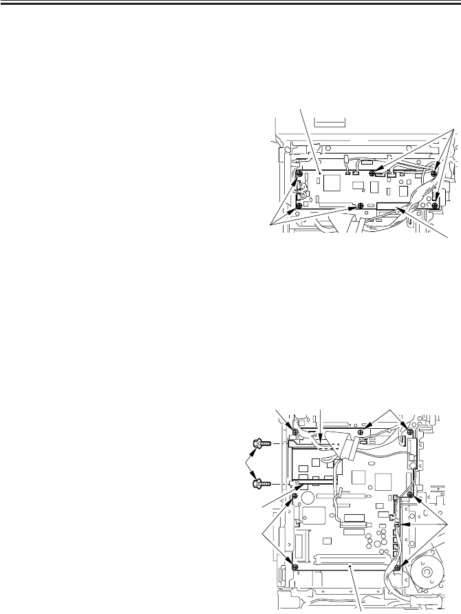
5.3.7 Removing the Reader Controller PCB
1) Remove the rear cover. (7 screws)
2) Remove the HDD unit. (p. 7-19P)
3) Disconnect all the connectors of the
harness.
4) Remove the six screws [1].
5) Disconnect the connector [2] to the
main controller, and detach the reader
controller PCB [3].
F07-503-07
5.3.8 When Replacing the Reader Controller PCB
“Troubleshooting”>Chapter 4 “Troubleshooting Image Faults/Malfunctions” >6.7 “Vari-
able Resistors (VR), Light-Emitting Diodes, and Check Pins by PCB”
5.3.9 Removing the Main Controller PCB
1) Remove the rear cover. (7 screws)
2) Remove the right rear cover. (5 screws)
3) Remove the DC controller PCB. (p. 7-
17P)
4) Remove the reader controller PCB. (See
item 5.3.7.)
5) Disconnect all the connectors of the
harness.
6) Remove the screw [1] (1 each), and de-
tach the two PCB guides [2].
7) Remove the eight screws [3], and detach
the main controller PCB [4].
F07-503-08
[3]
[1]
[1]
[2]
[3]
[2]
[3]
[3]
[1]
[2]
[4]
[3]


